


A pulley can turn freely on the bench and still be unsuitable for its intended cable installation. The groove, bearing interface and surrounding geometry must match the controlled assembly design. Aircraft control cable pulley manufacturing starts with those interfaces, not with a general catalogue diameter.
For a custom component enquiry, separate manufacturing feasibility from approval for aircraft use. The design authority defines the required geometry, materials, qualification and acceptance. A machining trial or a dimensionally correct sample does not independently establish airworthiness or authorize a substitution.
Identify the component boundary
Is the order for a bare sheave, a sheave with a bearing, or a larger assembly containing spacers and other parts? Put that answer on the quotation package. A bearing supplied by the customer still needs an identified specification and a defined installation responsibility.
Clarify which drawing controls the cable groove and which controls the assembled mounting relationship. A model can show a convenient overall shape without containing all the requirements needed to make an accepted part. Drawing notes and referenced specifications may define features that are not obvious in a rendered image.
The component should connect to the wider aerospace manufacturing processes plan through traceability, inspection and an agreed supply boundary. For Jucheng, the useful starting point is a controlled custom-part enquiry: what is to be machined, in which condition, and with what evidence at delivery.
Read the groove as a controlled profile
Outside diameter alone does not define the cable-contact geometry. The groove profile, root region, side features and their relationship to the rotational reference need to follow the design. Avoid deriving a replacement profile from a photograph or from an unidentified worn sample.
Review how the profile will be produced and measured. A form tool, a programmed turning operation or another route may be appropriate depending on material and geometry. The choice should be supported by access, tool control and inspection capability rather than by a preferred process name.
A profile measurement needs a defined reference and an agreed interpretation of transitions. Where the drawing contains a blended region, discuss how that region is evaluated. A few isolated diameter readings may not describe the complete contact surface.
Do not generalize cable size, bend relationships or installation clearances from another application. Those belong to the approved design and its supporting requirements. The manufacturing supplier’s task is to reproduce and verify the specified geometry, and to flag ambiguity before cutting material.
Compare material routes without assuming interchangeability
Aircraft Spruce lists phenolic and aluminum pulley constructions, but catalogue availability does not make them interchangeable. Their material properties, manufacturing routes and interface behavior differ. A custom part must use the designated material and condition unless a change is formally approved.
For an aluminum component, identify alloy, temper and stock form. Those details influence the machining plan and any subsequent treatment. The aluminum machining review should address wall support, feature access and the required condition after finishing.
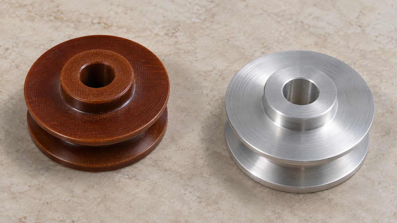
For a phenolic construction, specify the actual material system and supplied form. A broad label does not define reinforcement, orientation or the complete acceptance requirements. The cutting and inspection approach must suit that material, including the accepted condition of edges and machined surfaces.
| Decision | Aluminum route | Phenolic route |
|---|---|---|
| Material definition | Alloy, temper and stock specification | Specified material system, form and applicable orientation |
| Finishing discussion | Specified coating or treatment and dimensional allowance | Required machined condition and any specified treatment |
| Inspection planning | Final geometry and surface condition | Final geometry, edge condition and material-specific requirements |
| Substitution | Requires the responsible design authority’s review; similar size is insufficient | |
Coordinate the bearing seat with the assembly method
The bearing seat is a separate functional interface from the cable groove. Define its size, form, location and final condition using the controlled drawing. The bearing designation and installation method need to be available when reviewing that interface.
Do not choose an interference or clearance by habit. The required relationship depends on the specified materials, bearing arrangement and assembly design. If the drawing leaves the fit unresolved, raise that question rather than assigning a generic value in the quotation.
Inspect the relationship between the groove and the bearing reference, not just each feature independently. The manufacturing setup should explain how the reference is established and preserved across operations. Re-clamping can be practical, but the resulting relationship still needs a planned verification method.
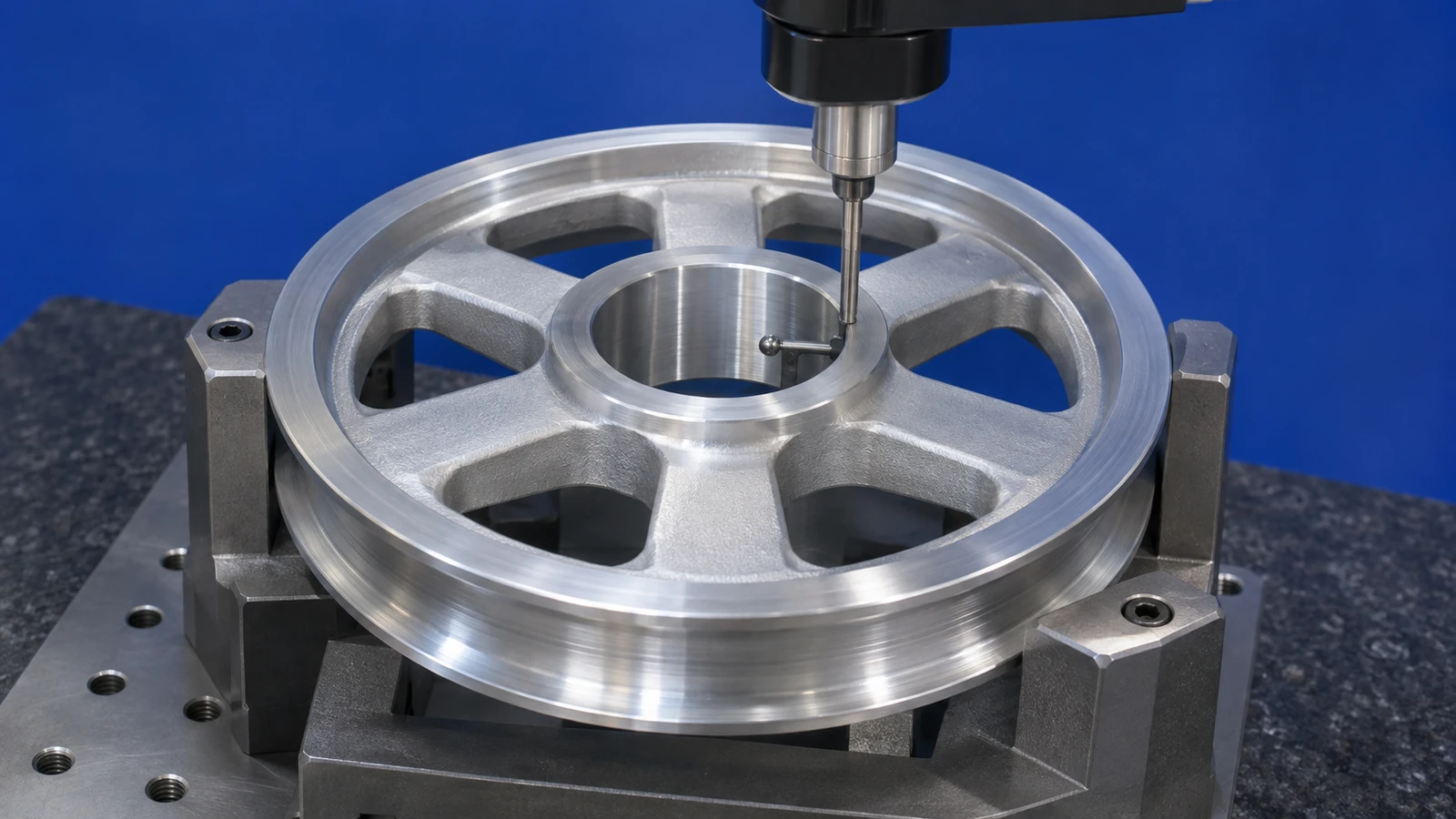
Where assembly is included, separate pre-assembly dimensional acceptance from post-assembly checks. A bore accepted before installation does not by itself show that the assembled unit meets the specified requirement. Equally, a unit that rotates does not establish all required dimensions or material conditions.
Leave room for the specified finish
A finished bore or groove should be accepted in the condition called out by the drawing. If a coating changes a functional surface, the process plan must account for it. Do not treat finishing as an appearance-only step added after final dimensions are approved.
Discuss masking, treatment boundaries and inspection stages with the finishing supplier. Some surfaces may require protection while others require the specified treatment. Those boundaries should be controlled rather than left to individual operator judgment.
Jucheng’s surface finishing services can be considered alongside machining during a feasibility review. The useful question is whether the combined route can deliver the defined final condition. A general list of available finishes is not a substitute for reviewing the actual drawing notes.
Keep the inspection package proportional to the risk
Plan measurements for the groove profile, bearing interface and their geometric relationship. Add material and finishing documentation required by the order. Identify any characteristic that needs a specialized method before promising a complete report.
Traceability should connect the delivered part to its material, drawing revision and inspection record. For prototypes, label any deviations or unfinished conditions explicitly. An experimental part should not be presented as equivalent to a released production component.
Discuss measurement access while the fixture and process route are still being developed. A feature that is easy to produce may be difficult to probe or view after assembly. The sequence should preserve the opportunity to collect the required evidence.
If the customer requires a first article package or other formal submission, agree its scope and format in advance. The term first article should not be used as shorthand for whatever measurements happen to be available. Define the required characteristics, documents and review responsibilities.
Turn the enquiry into a manufacturable specification
Send the part and assembly drawings, controlled model, material specification, bearing identification and finishing requirements together. Include the intended quantity and distinguish development samples from the later production requirement. That allows the supplier to discuss tooling and inspection without assuming that one route suits every stage.
For early work, use prototype manufacturing to answer a defined question: profile accessibility, feature relationship, finishing allowance or assembly feasibility. Record what the sample is meant to demonstrate so that the review stays focused.
The strongest manufacturing proposal explains the sequence and its checkpoints. It shows how the groove and bearing references will remain connected, when the final condition will be measured, and which requirements need clarification. That is more useful to an aerospace buyer than a broad claim that any pulley can be made.

