


A gearbox housing can pass a visual review and still fail its most important job: keeping shaft supports and gear interfaces in the relationship the assembly expects. The trouble often begins before finishing. Stock removal, setup changes, thin ribs, and clamping can shift the very bores that define the gearbox geometry. For an aircraft engine accessory gearbox housing, the machining plan should therefore be organized around the bearing and mounting references鈥攏ot around whichever surface is easiest to cut first.
This article follows that manufacturing problem from drawing review to inspection. It is intended for teams developing a component through aerospace prototyping and manufacturing; program-specific structural, engine, and airworthiness requirements remain with the responsible design authority.
Contents
- The symptom: individually correct features, poor assembly
- Build the datum scheme around the load path
- Leave room for stress release and finish machining
- Keep critical bores related across setups
- Tie material choice to housing function
- Measure the relationship, not just the diameter
- Questions to resolve before the first cut
- FAQ for sourcing and engineering teams
The symptom: individually correct features, poor assembly
Imagine a housing with two bearing bores, a mounting face, and a cover register. Each bore diameter may fall within its own tolerance, yet the shafts bind because the axes are not parallel or their center distance is wrong. The cover may bolt on while pinching an internal clearance. A flange can sit flat on the inspection table but rock against the mating structure because the datum relationship is not controlled as intended.
These are relationship problems. A list of isolated size checks cannot fully describe them. Review the assembly drawing and identify which features locate the housing, which support rotating elements, and which establish cover or accessory alignment. The resulting feature map should distinguish size, position, orientation, runout, and surface requirements where each is functionally needed.
That map also prevents over-inspection. A housing may contain many threaded holes and external surfaces, but not all have equal effect on assembly. Focus the process review on the features whose variation can propagate into gear mesh, bearing support, sealing, or mounting. The drawing must provide the limits; the manufacturing team can then plan how to preserve and verify them.
Build the datum scheme around the load path
Datums should reflect how the component is located and loaded in its assembly. A broad mounting face may be a primary reference, with dowel locations or a register controlling translation and rotation. If bearing bores are the functional centerline, the datum framework must make their relationship to the mounting interface measurable. Avoid choosing a convenient stock face as the production reference if it disappears before final inspection.
Think through the complete datum transfer: raw blank to first setup, first setup to secondary operations, and finished part to inspection fixture. Each transfer can introduce variation. A locating surface created early may be adequate for roughing but not for final bore alignment after substantial stock is removed. In some designs, finishing related bores in one controlled setup can reduce accumulated repositioning error; in others, tool access or part geometry requires separate operations. The released drawing and validated route determine the acceptable method.
Link the datum plan to manufacturing before release. A clear aerospace process plan describes which references are established when, which features are finished together, and where measurement checks protect the sequence. This is more useful than a generic promise of precision because it ties a method to the part’s actual geometry.
Leave room for stress release and finish machining
Gearbox housings can contain thick bosses connected by thinner webs and walls. Removing material asymmetrically may release residual stress or change how the blank sits in a fixture. Heavy clamping can also distort a thin region; the part may spring back after unclamping, moving a bore or face that appeared stable during cutting.
Review the stock form, machining allowance, and roughing sequence together. A staged route may rough major pockets, preserve support around critical features, allow the part to stabilize where appropriate, then finish datums and bores. The exact sequence depends on material, geometry, and program needs; it should be agreed and documented rather than assumed. If a supplier proposes a different blank or fixture, check whether it changes the material condition or datum references.
Thin walls deserve their own control plan. Avoid using a low-stiffness wall as the sole clamping surface when a more stable pad or temporary support is possible. Consider whether finishing both sides in a balanced manner could reduce uneven material removal. These are manufacturability considerations, not substitutes for the design authority’s structural analysis or the specified geometry limits.
Keep critical bores related across setups
Every setup change is a chance to lose the relationship between features. Before machining, establish which bores, registers, and mounting faces can be reached from a shared reference. If the work requires a new orientation, define how the part will be located and how the setup will be verified. A repeatable fixture can help, but only if its locating points correspond to controlled product datums and the fixture itself is maintained.
Tool reach matters too. A long tool may access a deep bore but flex under load; a shorter tool may be more rigid but require a different approach direction. A cutter’s reach can influence surface condition, edge formation, and cycle sequence. Review intersecting bores for burrs and cleaning access, and avoid leaving a critical internal edge dependent on an undocumented manual operation.

After roughing, an in-process check can determine whether the remaining stock and reference features still support the planned finish cut. After final machining, the inspection method should relate the bore axes to the mounting datums. The proper approach may use precision gauging, coordinate measurement, or an approved fixture, depending on the feature and requirement. Do not interpret a numerical result without confirming the datum alignment and measurement setup.
Tie material choice to housing function
Material decisions should consider stiffness, strength, temperature, vibration, lubrication environment, corrosion exposure, mass, and the housing’s role in supporting the accessory train. An aluminum housing may be attractive for mass and machining considerations in some applications; an alloy steel or other specified material may be selected where the design requires different structural or environmental behavior. No broad material category determines suitability by itself.
Specify the exact alloy, product form, condition, and documentation required. The manufacturing supplier should not substitute a similar-sounding grade without approval. Material properties quoted for a handbook or typical specimen do not guarantee the behavior of the actual finished component, especially when orientation, heat treatment, and section size differ. The aerospace materials overview can organize early comparisons, while the drawing and approved procurement documents govern the actual build.
Finish also interacts with fit. Coatings or conversion treatments can change dimensions at bores, registers, and fastener interfaces. Identify areas to mask, dimensions to inspect after finishing, and whether any post-finish rework is allowed. If the housing uses inserts, sleeves, or threaded features, specify the sequence and acceptance method rather than relying on visual appearance.
Measure the relationship, not just the diameter
Inspection should answer the same questions as the design: Are the bores the right size? Are their axes where they need to be relative to one another? Do the mounting face and registers locate the housing as intended? Is the final part evaluated in a defined condition? A report that lists bore diameters without positional context may leave the main assembly risk unanswered.
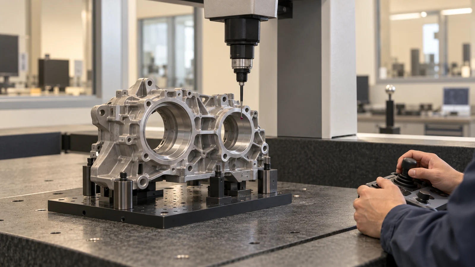
Build a characteristic-to-evidence matrix. For each critical feature, identify the drawing requirement, measurement method, setup datum, inspection stage, and record. If a bore becomes inaccessible after installing a sleeve or closing a cover, capture evidence before that operation. If a finishing step can alter a critical dimension, repeat the relevant check afterward.
Measurement uncertainty and access should be considered during design review. A deep bore may require a suitable probe or gauge; a complex housing may benefit from a coordinate-based inspection strategy. The method must be capable of evaluating the actual geometric control, not merely produce a number. For nonconforming results, define who can authorize disposition and how any rework is recorded.
Questions to resolve before the first cut
Ask the manufacturing team to explain how it will establish the primary mounting reference, preserve bore relationships, support thin walls, and verify the setup after each major orientation change. Request a review of stock condition, roughing allowance, critical inspection stages, and any features that will become hidden after assembly. These questions expose risk before it is embedded in tooling or a work order.
Also align the data package: current model, controlled drawing, revision, material specification, finishing notes, and inspection requirements. Call out any model-drawing mismatch and name the document that controls. When a design change shifts a bore or mounting pad, describe the affected interfaces so the supplier can reassess both machining and inspection rather than changing one feature in isolation.
A well-managed prototype does not prove every future operating condition. It does, however, allow the team to assess whether the datum scheme, machining route, assembly interfaces, and inspection evidence work together. That is the useful outcome of treating the gearbox housing as a coordinated mechanical system rather than a collection of dimensions.
FAQ for sourcing and engineering teams
Why can correct bore diameters still produce binding?
Diameter controls size, not necessarily the position, orientation, spacing, or alignment of the bores. The assembly drawing must define those relationships and inspection must evaluate them from the intended datums.
Should all critical bores be machined in one setup?
That can reduce repositioning when geometry and tool access allow it, but it is not universal. The route should be selected against the part design, fixture stability, and specified inspection requirements.
Can the supplier choose a substitute alloy?
Not without approval. Material grade and condition are part of the product definition and may affect structural, thermal, and finishing behavior.

