


An aircraft fuselage frame is a structural cross-section that helps maintain the body shape and provides attachment points for skins, floors, systems, or neighboring structure. Manufacturing decisions depend on whether the frame is formed, machined, built up, or integrated with other parts, and on how its datums relate to the fuselage assembly. The critical challenge is preserving the intended shape and interfaces through forming, material removal, and inspection.
This article is about component manufacturability and supplier coordination. It does not replace structural design, airworthiness analysis, or program approval. A frame prototype should be ordered to answer a specific question about geometry, fit, tooling, or process feasibility.
Contents
- Start with the frame’s role in the fuselage
- Formed, machined, and built-up frames are not interchangeable
- Datum transfer controls the assembly shape
- Support the frame without forcing it into shape
- Inspection should connect part geometry to the assembly
- Supplier questions worth resolving before release
- Frequently asked questions
Start with the frame’s role in the fuselage
Frames can have different cross-sections, thicknesses, cutouts, flanges, and local reinforcements. One frame may support a floor or system bracket; another may maintain a shell contour or connect to a larger structural assembly. The manufacturing plan should identify which edges, faces, and holes establish the frame’s position in the fuselage.
Review the frame with its adjacent skin, stringers, clips, and mating structures. A nominal contour does not communicate all assembly needs. The drawing should identify datums, edge conditions, fastener patterns, and any controlled profile or gap requirements. If the assembly coordinate is important, provide the reference information needed to reproduce it.
The broader Aviation and Aerospace manufacturing page provides the industry context, while the frame drawing should define the actual part-level acceptance criteria.
Formed, machined, and built-up frames are not interchangeable
Formed sheet can suit frames designed around bends and flanges. Machining can create integrated pockets or features from a solid blank, though material removal and support become important. A built-up design may combine members or fittings through joining and fasteners. The approved drawing and material specification determine the allowed route; changing between them may change strength, residual stress, or assembly behavior.
| Route | Good question to ask | Risk to manage |
|---|---|---|
| Formed frame | How are bend allowances, springback, and flange angles verified? | Free-state profile differs from the assembly reference |
| Machined frame | How will the part be supported as pockets and thin walls are cut? | Release movement changes the profile or hole relationship |
| Built-up frame | Which assembly fixture and joining sequence control the final geometry? | Accumulated fit-up variation shifts the attachment points |
For a formed design, the sheet metal fabrication process may be relevant. For complex machined features, the five-axis CNC machining process can be reviewed where tool access and setup geometry support it.
Datum transfer controls the assembly shape
A fuselage frame may be inspected as a free part, held in a checking fixture, or evaluated in a larger assembly. Each condition can produce a different result if the datum scheme is not clear. The buyer and supplier should agree which condition governs acceptance and how the part is supported during measurement.
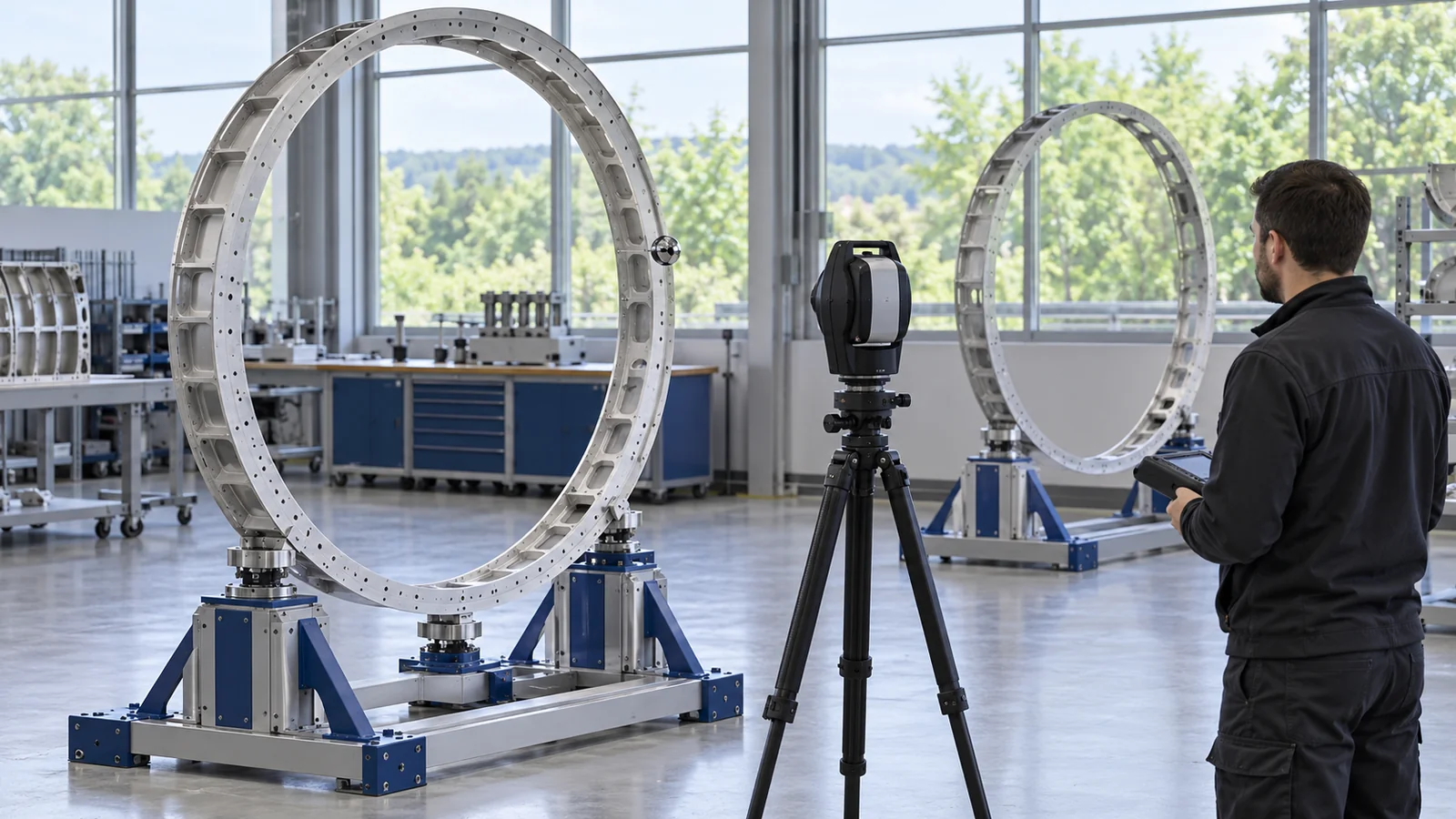
When a frame is formed, the sequence from flat blank to finished contour can move features relative to one another. When it is machined, the location of the first setup and the choice of support points affect later operations. When it is assembled, fixture and joining order can change the final free-state condition. A datum-transfer map helps the team see where each process introduces a new reference.
Keep the inspection setup tied to the drawing’s datum reference frame. A supplier’s convenient fixture is useful only if it reproduces the required relationship and does not conceal a mismatch by forcing the frame into place.
Support the frame without forcing it into shape
Large, light structures can flex under their own weight or under clamp force. A measurement taken with a frame resting on an arbitrary surface may not match the specified condition. Likewise, a fixture that clamps the frame to nominal can mask whether the free part meets its profile requirement.
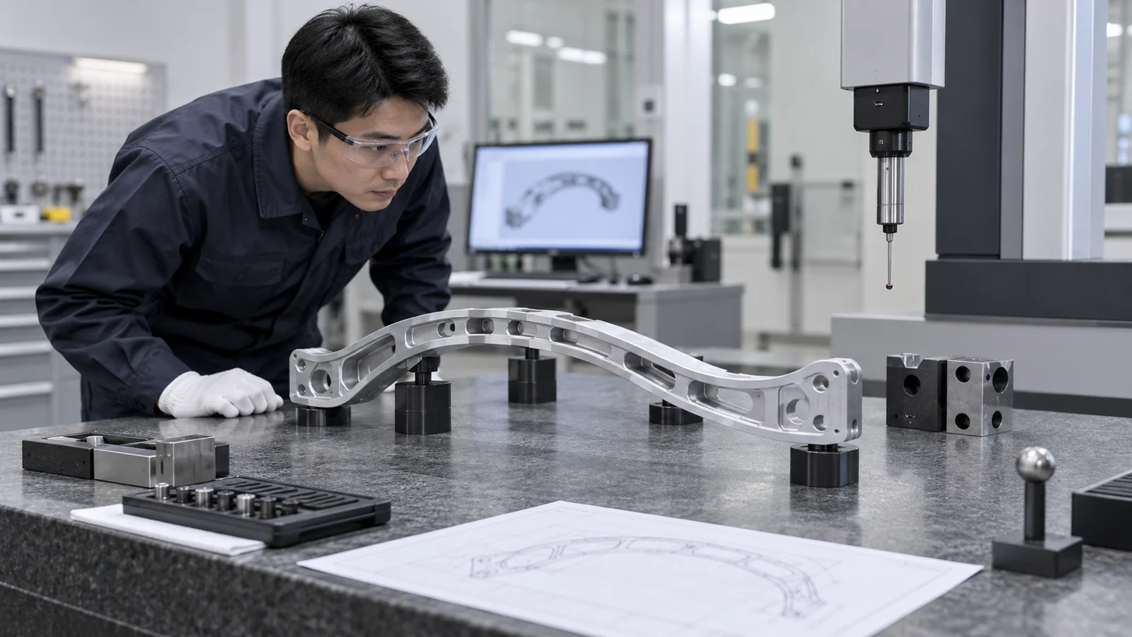
Define support locations and any restraint used during inspection. If the drawing specifies a free-state or assembled condition, use that as the measurement basis. During manufacturing, locate fixtures near stable features and avoid unnecessary clamp loads on thin sections. The actual support strategy should be reviewed against the geometry and process route.
For machining, distinguish tool deflection from part movement and fixture movement. For forming, distinguish springback from measurement setup variation. For an assembly, distinguish local gap-up from a global datum shift. This makes corrective action more specific than simply “adjust the fixture.”
Inspection should connect part geometry to the assembly
A useful inspection plan links profile, hole position, flange angle, and attachment points to the fuselage datums. Some features may be checked with a coordinate measuring system; others may use a template, dedicated fixture, or calibrated manual instrument. The method should be capable of measuring the specific characteristic and should be recorded with the part revision.
Where the frame is part of an assembly, identify which relationships require an assembly-level check. A part inspection report may confirm the individual features but does not automatically verify a fuselage-level interface. If the critical gap or attachment relationship is only visible after integration, plan a corresponding check at that stage.
For prototype work, preserve the raw measurement results and note any temporary fixture or material differences. Do not convert a fit check into a claim of structural performance or production qualification.
Supplier questions worth resolving before release
Provide the released drawing and model, material and condition, quantity, process constraints, finish, datums, critical features, inspection condition, and required records. Include the mating assembly context where permitted. Explain whether the first article is for geometry, assembly fit, or process learning.
Ask the supplier how the part will be supported, where datum transfer occurs, how the free-state shape will be checked, and which features become inaccessible after forming or assembly. If a process change is proposed, require the responsible design authority to approve it before production.
For a long-lead material or a large blank, resolve the documentation and inspection needs before purchase. This avoids discovering after machining that a required traceability record or acceptance condition was not in the order.
Frequently asked questions
Are aircraft fuselage frames usually formed or machined?
Both routes exist, along with built-up designs. The frame geometry, material, quantity, and approved program definition determine which process is acceptable.
Why can a frame pass inspection in a fixture but miss assembly fit?
The fixture may force the part into nominal or use a different datum reference from the fuselage assembly. The acceptance condition and support points need to match the drawing intent.
Does a prototype frame prove structural performance?
No. A prototype can support geometry, fit, or process evaluation. Structural qualification and aircraft approval require separate engineering and test evidence.
What should a supplier see besides the part drawing?
Where permitted, provide the mating interfaces, assembly datums, material condition, inspection expectations, finish, quantity, and the prototype’s intended purpose.
Fuselage-frame sourcing works best when the buyer aligns the manufacturing route, support condition, datum transfer, and assembly check before releasing the RFQ. That helps a supplier deliver a measurable component without treating a local fit check as approval of the complete airframe.

