


An aircraft instrument panel can be accurately cut and still fail its first fit check. The usual causes are not mysterious: a cutout was taken from a generic catalog dimension, a mounting reference was assumed instead of defined, or a late avionics change shifted the layout without updating the released drawing. A reliable panel starts with controlled interface data, then turns that data into a manufacturable flat pattern and a fit-check plan.
This guide is for engineers, avionics integrators and procurement teams preparing a custom panel, replacement panel or prototype. It focuses on manufacturing handoff-not aircraft modification approval, avionics installation instructions or airworthiness acceptance. The aircraft’ approved design data and the equipment manufacturer’ current installation drawings remain authoritative.
- Begin with the interfaces, not the blank
- Turn equipment data into controlled geometry
- Build the cutout plan around real assembly access
- Choose a material and process route that fits the stage
- Use a test panel to expose hidden assumptions
- Close the job with inspection and revision evidence
- Frequently asked questions
Begin with the interfaces, not the blank
An instrument panel is a structural and packaging interface between the airframe, instruments, avionics, switches, controls and the person who must reach them. Its outline is only one part of the product definition. Before selecting stock or programming a router, identify the aircraft reference points, panel mounting features, adjacent supports and equipment envelopes that constrain the layout.
Ask the design owner to identify the primary datums and the surfaces that seat against the airframe. If the panel is segmented, define how each section locates to its neighbor. If the design uses brackets or backing plates, include their thickness and stack-up in the model. Otherwise, a faceplate may look correct in CAD while a connector, fastener head or instrument clamp collides behind it.
Separate the critical interface dimensions from cosmetic spacing. A mounting-hole pattern, instrument opening and control clearance can each serve a different function. The drawing should show which relationships control assembly and which dimensions simply describe appearance. This distinction helps the manufacturer plan inspection around meaningful acceptance characteristics rather than measuring every line with equal effort.
Turn equipment data into controlled geometry
For each instrument or display, use the current manufacturer installation drawing rather than a generic cutout library as the final authority. Catalogs and panel-design tools can accelerate layout, but their dimensions may be starting values, may apply to a specific bezel or clamp, or may omit rear clearance. Aviat Group’ panel-design tool cautions users to verify starter dimensions against manufacturer installation drawings; that is a useful reminder for any panel release.
Convert the equipment schedule into a cutout table. For each item, record the controlled part number or model, face dimensions, cutout geometry, mounting method, connector projection, required access and source revision. If a device has several approved mounting options, record which one the design uses. Do not let a shop infer the intended geometry from a product photograph.
| Panel feature | What to define | Why it matters in fabrication |
|---|---|---|
| Instrument aperture | Shape, size, orientation and reference location | Controls bezel fit and the relationship to adjacent equipment |
| Mounting pattern | Hole size, position datum, edge margin and fastener access | Prevents a faceplate that cannot be secured or serviced |
| Electrical opening | Connector body, strain relief and cable bend envelope | Protects rear clearance and installation access |
| Panel perimeter | Mounting faces, edge treatment and local contour | Controls fit against the cockpit structure and supports |
When the source drawing and the panel model disagree, stop and resolve the discrepancy before cutting. A buyer should be able to trace each critical opening back to an approved source. This traceability is especially important after equipment substitutions: the new unit may share a nominal face size yet use different clamp hardware, connector depth or cooling clearance.
Build the cutout plan around real assembly access
A flat panel is easy to inspect on a table. The assembled cockpit is not. Check whether a technician can reach retaining nuts, plugs, backshells, circuit breakers and fasteners after the panel is installed. Confirm that the instrument can be removed without dismantling unrelated hardware. A cutout that fits the device but blocks a tool path is still a design problem.

Review minimum material between adjacent openings, around the perimeter and near fasteners. The acceptable web width depends on material, panel thickness, load path and approved design requirements; do not copy a generic number from a different aircraft. The manufacturer can flag a narrow bridge or a sharp internal corner as a fabrication risk, but only the responsible design authority can approve a geometry change.
Also plan for edge quality. Small burrs can complicate installation, snag wiring or create local damage during handling. The drawing or purchase specification should state the required edge condition and identify any edges that must remain sharp, deburred or protected. Keep this instruction consistent with coating, engraving and marking operations so later finishing does not obscure a critical feature.
Choose a material and process route that fits the stage
For a design still being checked, a clear polymer test panel can reveal whether instruments, fasteners and wire bundles collide before final metal is cut. Mid Atlantic Panels describes using a clear polycarbonate test fit before fabricating an aluminum panel; the value is not that every project must use the same sequence, but that a low-cost physical check can expose layout assumptions that a screen review misses.
For a released metal panel, CNC routing, milling, laser cutting or waterjet cutting may be considered according to geometry, stock, edge requirements, quantity and downstream finishing. These are not interchangeable by default. The selected method must preserve required feature quality and leave enough control for secondary operations such as countersinking, edge finishing, coating and marking.
For design teams comparing the available routes, the Aviation & Aerospace prototyping and manufacturing overview is a relevant starting point for the project context. It does not replace a process review of the actual panel drawing, material condition or acceptance criteria.
Use a test panel to expose hidden assumptions
A fit check is most useful when the team decides in advance what it is meant to prove. A paper template may confirm approximate spacing. A clear test panel can expose behind-the-panel interference. A machined prototype can verify edge quality, fastener engagement and a more realistic assembly stack. None of these checks automatically validates electrical behavior, structural performance or aircraft-level approval.
Before the check, identify the aircraft or fixture reference, the equipment configuration, the fasteners and supports to be used, and the observations to record. Mark each change against the same drawing revision. If a connector or instrument is unavailable, document the surrogate and the limitation instead of treating an incomplete fit as a pass.
Close the job with inspection and revision evidence
The inspection plan should connect each acceptance characteristic to a measurement method. A coordinate measuring system or optical measurement may suit a complex pattern; calipers, gauges or a fixture may be more appropriate for other features. The chosen method depends on tolerance, access and the released inspection requirement. A panel inspection report should identify the part, drawing revision, material and measurement status without claiming checks that were not performed.
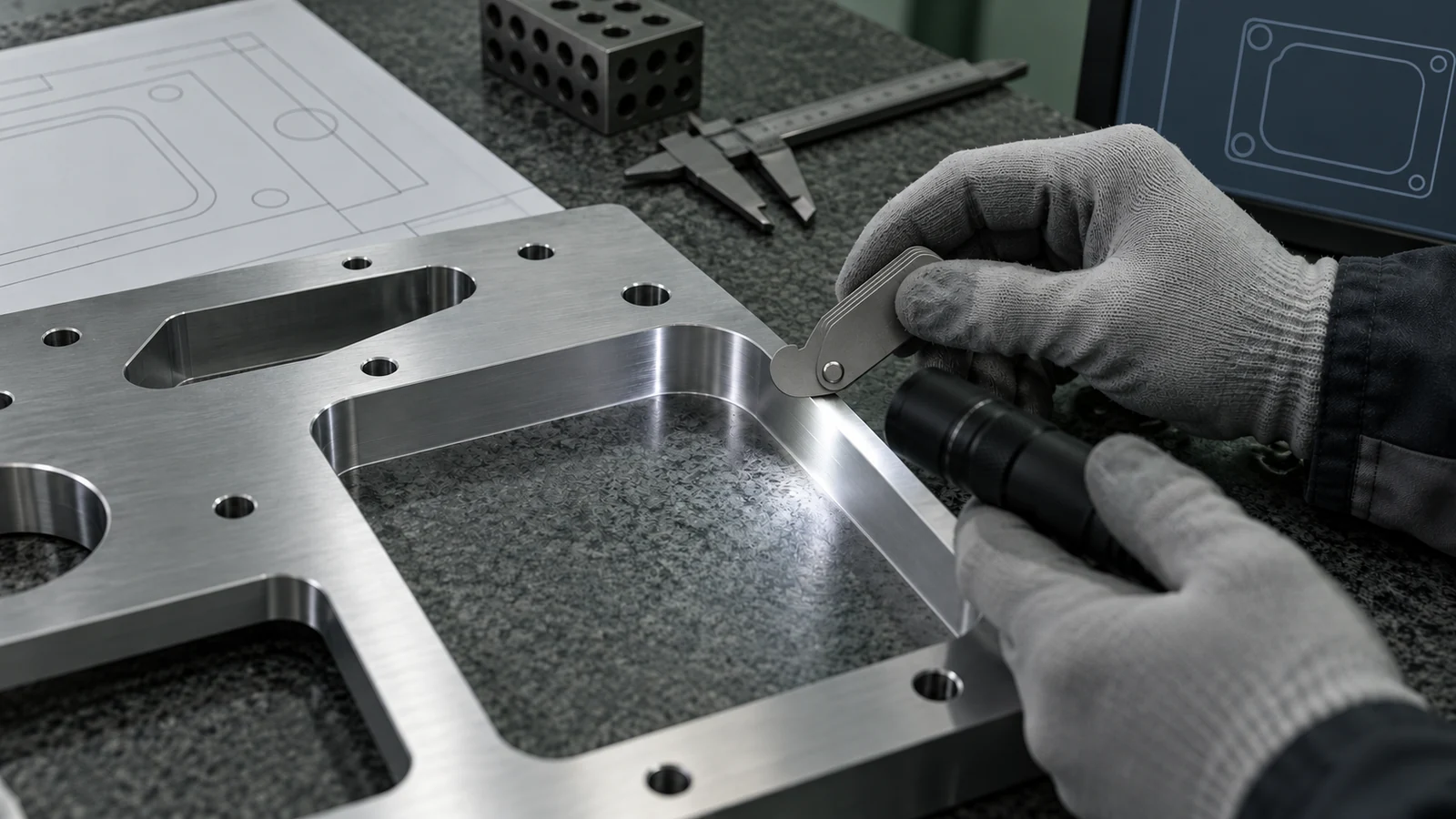
For a repeat order, preserve the controlled model, manufacturing revision and approved equipment list together. If one instrument changes, identify every affected cutout, wire clearance and mounting relationship. A quote should make assumptions visible: who supplies the latest installation data, whether finishing is included, what inspection records are delivered, and how revisions are handled after programming begins.
Frequently asked questions
Can a generic instrument cutout library be used for production?
It can help start a layout, but it should not replace the current installation drawing for the exact instrument and mounting configuration. Verify cutout dimensions, clamp details, connector clearance and revision before releasing the panel for fabrication.
Why make a transparent test panel first?
A transparent test panel can reveal rear-side interference, fastener access and wire clearance that are difficult to judge from a front view. It is a fit-check aid, not proof of structural or electrical qualification.
Which process should make an aircraft instrument panel?
The route depends on the released material, geometry, edge and hole requirements, quantity, finishing and inspection plan. CNC routing, milling, laser or waterjet cutting may be considered, but the project drawing and approval path determine what is acceptable.
Bottom line: the fastest way to avoid a panel remake is to make every cutout traceable to an approved equipment source, define the airframe datums, test the rear-side envelope and control revision changes before the final blank is processed.

