


An aircraft propeller hub is the central mechanical interface between the propeller blades and the rotating shaft or drive system. Its manufacturing challenge is not just producing a complex outer shape. The bore, blade-root seats, retention features and reference surfaces must remain related so the assembly can be evaluated against its released definition.
This article looks at new-part machining and engineering handoff for prototype or build-to-print work. It does not provide propeller design, maintenance or airworthiness guidance. The program drawing, approved materials and responsible design authority govern the actual component.
- Separate the hub from the complete propeller system
- Define the shaft and blade-root interfaces first
- Plan setups around concentricity and access
- Keep material and process decisions traceable
- Measure the features that establish the assembly
- Make the quote reflect the real scope
- Frequently asked questions
Separate the hub from the complete propeller system
Search results for aircraft propeller hubs include large-part machining demonstrations and manufacturer material about complex five-axis work. Okuma’s aircraft-industry example describes a propeller hub and emphasizes reducing setup changes on a large, complex workpiece. The practical lesson for a buyer is to ask how a supplier will preserve feature relationships through the route, not to assume that one machine configuration guarantees a conforming part.
A hub may be one item in a larger assembly involving blades, retention hardware, pitch mechanisms and a shaft interface. A quote for the hub alone should identify whether material supply, heat treatment, finish, marking, inspection or matched assembly is included. Do not treat an individual machined hub as evidence that a complete propeller system has been balanced, tested or approved.
Define the shaft and blade-root interfaces first
Start the drawing review with the interfaces that locate and retain the hub. Identify the shaft bore or mounting face, blade-root seats, bolt circles, key or spline features, retention hardware and any pitch-related interfaces that are part of the component scope. State which surfaces establish the datum reference frame and how the hub is oriented during inspection.
For a multi-blade hub, the angular relationship between blade stations may matter as much as each local pocket. Clarify whether positions are controlled from a common axis and clocking datum or by separate dimensions. If the engineering definition uses a model for a complex surface, record its exact revision and acceptance method. The manufacturer should not infer a pitch angle, retention load or fit from a generic illustration.
| Interface | Why it deserves early review | What the drawing package should identify |
|---|---|---|
| Shaft mounting bore or face | Locates the hub on the rotating system | Datum, fit definition, axis and inspection reference |
| Blade-root seat | Transfers load and establishes blade position | Contact geometry, retention method and angular relationship |
| Fastener or retention feature | Can constrain assembly and service access | Hole pattern, thread form, edge condition and supplier scope |
| Pitch or control interface | May coordinate movement across the assembly | Controlled geometry and program-specific acceptance data |
When geometry or source data conflicts, place the item on a clarification list. Do not resolve it by changing a nominal value in CAM or choosing whichever drawing view appears clearest.
Plan setups around concentricity and access
Hub geometries can combine a central bore, radial blade features, fastener holes and curved external surfaces. A manufacturing plan should identify which operations share a setup and which require reorientation. Each re-clamping step creates a datum-transfer question: what feature locates the part next, and how will that relationship be checked?
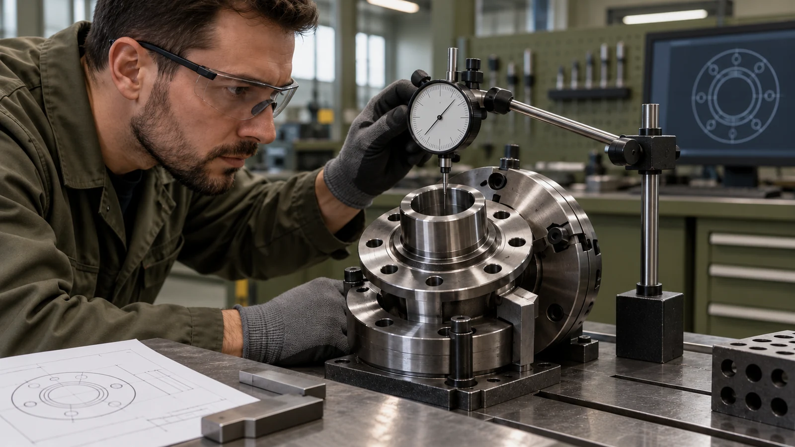
Multi-axis machining can reduce repositioning for some complex shapes, but it is not automatically the lowest-risk route. A supplier should review tool access, holder clearance, workholding, chip evacuation and inspection access together. A toolpath that can reach the surface may still leave a difficult setup for measuring the blade-root interfaces or internal bore.
Consider the material-removal sequence. Roughing a large mass unevenly can alter the part’s stability, and final finishing may require a more controlled support. The actual method depends on the approved material and geometry. The RFQ should not prescribe a machine brand or a universal setup count unless the program specifically controls it.
Keep material and process decisions traceable
Hub material is not a generic choice between aluminum and steel. The released definition determines alloy, product form, temper or heat-treatment condition, and any source restrictions. A substitute with a similar family name is not automatically equivalent. Buyers should specify the material record required and how it links to the part and drawing revision.
Finishing can affect fits, contact surfaces or dimensions. State whether critical dimensions apply before or after coating or other treatment, and identify areas that must be masked or protected when the design requires it. If an operation is outside the machining supplier’s scope, make the handoff point clear so the delivered condition is not ambiguous.
For wider project context, the Aviation & Aerospace prototype and manufacturing overview can help frame the route across design and manufacturing stages. It should not be read as a specification for any particular hub.
Measure the features that establish the assembly
A useful inspection plan connects each critical interface to a measurement method. The bore axis, blade-root seats, clocking, mounting face and retention features may require different checks. A coordinate measuring machine, dedicated gauge or other suitable equipment can be considered according to geometry and acceptance limits; the released plan determines what constitutes acceptance.
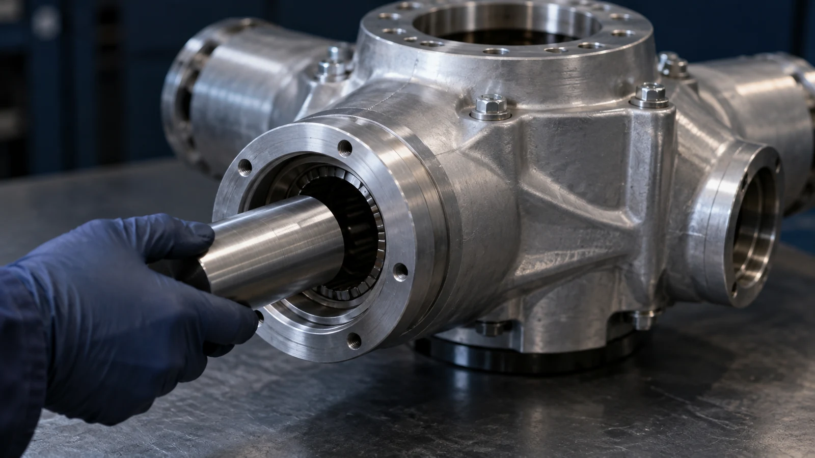
Make accessibility part of the design review. Can the probe reach a pocket wall? Can a gauge locate from the same datum as assembly? Are internal transitions visible or otherwise inspectable? If the answer is no, the team may need an approved fixture, alternate measurement approach or design clarification before production.
Dimensional inspection of a hub does not by itself verify assembly balance, vibration behavior, blade tracking or aircraft performance. Keep part acceptance separate from system validation, and state which party owns each test and record.
Make the quote reflect the real scope
A supplier-ready package includes the released drawing and model, material and condition, quantity, finishing requirements, inspection characteristics, documentation, packaging and revision status. It should also say whether blades, retention hardware or assembly work are included. Ask the supplier to identify risks involving setup changes, access, datum transfer and inspection before accepting a schedule.
- Define the exact component boundary and mating parts.
- Identify the shaft datum and blade-root references.
- Provide controlled material and finish requirements.
- State inspection records and any separate system-level tests.
- Distinguish prototype evaluation from production release.
Frequently asked questions
Does a machined hub prove the propeller is balanced?
No. Part-level geometry and assembly-level balance are different acceptance questions. A hub inspection report should not be presented as proof of the complete propeller’s balance or performance unless the approved test scope actually includes those checks.
Is five-axis machining required for every aircraft propeller hub?
No universal process applies. Five-axis or other multi-axis work may suit some complex geometries, while another route may be appropriate for a different size, material or feature set. The supplier should explain the setup and inspection plan against the released definition.
What is the most important information for a hub RFQ?
Identify the controlled shaft and blade interfaces, material condition, drawing/model revision, inspection criteria and whether assembly or system tests are in scope. These details make quotes more comparable and reduce assumptions.
Bottom line: hub manufacturing should protect the reference relationships that connect the shaft, blade roots and retention features. Define those interfaces first, plan datum transfer explicitly and keep part inspection separate from propeller-system validation.

