


The cutting flute gets most of the attention on an orthopedic bone reamer, but it is only one part of the manufacturing problem. The drive interface, body stiffness, edge condition, runout, surface finish, and cleaning access all affect whether the finished instrument matches its drawing and its intended device configuration.
Orthopedic bone reamer manufacturing is best planned as a coordinated set of interfaces and evidence. This article discusses component design and supplier handoff, not surgical technique or clinical selection. Reamer designs vary by intended use, reusable or single-use status, and device system, so the released specification and regulatory owner define what applies to a particular instrument.
Read the reamer as a set of functional features
A reamer may include a cutting head, flutes, a pilot or guide feature, a shaft, a coupling or drive end, and transitions between sections. Not every model uses the same arrangement. For a supplier, the first task is to identify which features control cutting, guidance, connection, and inspection, then map those functions to the drawing’s datums and tolerances.
Do not infer clinical use or acceptance criteria from a product photograph. A family of reamers can share a general form while differing in diameter, cutting geometry, drive interface, surface condition, or use instructions. FDA’s product classification database lists a device reamer as an orthopedic manual surgical instrument under product code HTO, but that classification entry is context—not a substitute for the applicable device-specific specification or regulatory review. See the FDA device reamer classification.
The drawing review should begin with the controlled interface: how the reamer is driven or retained, what aligns the cutting head, and which surfaces are inspected relative to that connection. Then identify the cutting edges, flutes, relief surfaces, and transitions that require a defined edge condition. This keeps the manufacturing discussion anchored to the part rather than to assumptions about how a surgeon will use it.
Feature map: what to machine and verify
A compact feature matrix helps separate operations from acceptance evidence. It also makes a useful supplier review tool when the drawing is dense or the model has several closely related variants.
| Feature group | Why it matters to the part | Manufacturing or inspection question |
|---|---|---|
| Cutting edges and flutes | Define the specified cutting profile and relief | How is edge geometry protected and checked after finishing? |
| Pilot or guide feature | Relates the tool axis to the cutting region | Is position/runout referenced to the correct datum? |
| Drive or coupling interface | Connects the instrument to its mating component | Are fit, retention, orientation, and engagement independently defined? |
| Transitions and slots | Can concentrate stress or retain residue | Can the area be inspected and cleaned as specified? |
| Surface and material condition | May affect finish, wear, corrosion behavior, or downstream treatment | Which condition is required at each inspection point? |
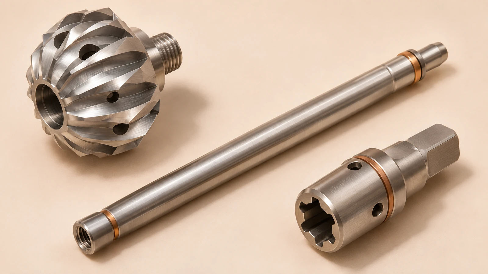
The matrix is not a replacement for geometric tolerancing. It is a way to catch incomplete handoffs before a manufacturing plan is locked. A diameter may control a fit while the feature-control frame controls the axis relationship. A visual edge note may define a different condition than the specified cutting profile. Keep each requirement tied to its drawing callout.
Protect the cutting geometry through the process
Flute form, relief, edge location, and the transition into the cutting region should be treated as a connected geometry. A process that reaches the nominal profile but leaves an uncontrolled burr or changes the edge during polishing may not meet the intended drawing condition. Decide which operations establish the geometry and which operations are allowed to remove material afterward.
Tool access can shape the route. The head may require indexed milling, turning, grinding, EDM, or a combination depending on material, geometry, quantity, and specification. These are possible process families, not a blanket claim that one route suits every design. The drawing should identify the required form and finish; the supplier can propose a feasible sequence and state assumptions about edge finishing and inspection.
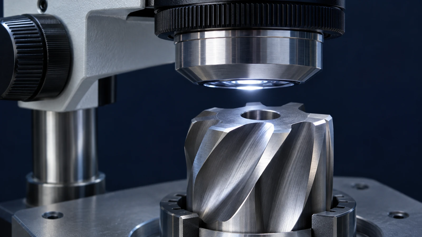
Protect finished edges during later handling and secondary operations. A small contact mark near a cutting edge may be functionally different from a mark on a noncritical shaft surface. Define acceptance by location and characteristic rather than relying on a general cosmetic standard. If the design includes multiple flutes or repeated teeth, the inspection plan should state whether it samples key features or verifies a full profile.
Control the drive and alignment interfaces
The drive end is not merely a convenient way to hold the part. It often provides the reference used to establish the tool axis and may include a keyed shape, coupling slot, flat, or other retention geometry. If the cutting head is machined in a different setup, the transfer between the drive datum and head datum needs a repeatable method.
Check concentricity, runout, angular orientation, and axial location only where the drawing calls for them and relative to the stated datum frame. “Runout” is not a catch-all substitute for position or profile. If the drawing does not define the required relationship, ask the design owner to clarify it before a supplier invents an acceptance limit.
Connection features should be evaluated with the mating interface in mind. The customer can provide a mating part, interface drawing, or controlled gauge specification if those are part of acceptance. A representative gauge may answer one fit question; it does not necessarily establish every dimensional relationship in the drawing. Record what it verifies and what remains to be inspected separately.
Treat material and finish as drawing-controlled inputs
Instrument designs may specify different stainless, precipitation-hardening, or other materials and conditions. Do not substitute by broad material family. The exact grade, condition, heat treatment, coating, and surface-finish requirements should be taken from the controlled documents. If a material certificate or traceability record is required, name it in the purchase package rather than assuming it is included.
Surface finishing can alter an edge, obscure a small feature, or change a dimension. Establish whether measurement occurs before or after the specified finish and identify surfaces that must remain protected. If an abrasive or electropolishing step is contemplated, the responsible design authority should approve its effect on edge geometry and the acceptance method.
The same discipline applies to cleaning. A clean-looking exterior does not prove that every flute, channel, or enclosed feature meets a documented cleanliness requirement. Specify the cleanliness target and evidence required for the part. If the device is reusable, cleaning and reprocessing instructions belong to the device manufacturer’s validation and labeling responsibilities; a component machining supplier should not claim that a machined part is sterile or clinically ready.
Design inspection and cleaning access into the handoff
Complex flutes, slots, intersections, and blind regions can be hard to inspect after finishing. During design review, identify which surfaces can be measured directly, which need optical or tactile methods, and which are hidden after assembly. If the device design depends on cleaning access, consider how the specified geometry can be inspected and how the device will be validated for its intended cleaning process.
FDA notes that reusable medical devices need device-specific reprocessing steps and that narrow lumens, hinges, sleeves, and adjacent surfaces can present cleaning challenges. That guidance is relevant to design-for-cleanability discussions, but it does not establish the cleaning validation for a particular reamer. See [FDA information on factors affecting reusable-device reprocessing](https://www.fda.gov/medical-devices/reprocessing-reusable-medical-devices/factors-affecting-quality-reprocessing).
For a first article, agree on the inspection plan before the final operation. Identify the part and drawing revision, the datum simulation, the profile or edge characteristics, measurement method, and report format. If a feature cannot be inspected with the proposed setup, resolve that gap before the part is accepted rather than treating a process description as evidence.
Jucheng’s related acetabular cup machining article and bone screw machining overview cover different orthopedic components. A reamer article should remain focused on the instrument’s cutting geometry and interfaces, not duplicate implant-component material selection or clinical guidance.
FAQ
Is an orthopedic bone reamer the same product as an arthroscopic shaver?
No. They are distinct instrument types with different cutting geometries and interfaces. Manufacturing articles should describe the specified component and avoid merging them under a generic “surgical cutter” topic.
Does FDA classification mean every reamer has the same requirements?
No. The product classification entry is a regulatory database reference, not a complete device-specific specification. Intended use, design, labeling, and applicable requirements must be reviewed for the particular device.
Can a polishing operation be added after machining without changing acceptance?
Not automatically. Finishing can alter edges, profile, dimensions, or surface condition. The process and inspection sequence should match the drawing and be approved by the responsible design authority.
What belongs in a reamer manufacturing RFQ?
Provide the controlled drawing and model, exact material condition, edge and profile requirements, drive-interface details, finish or coating, traceability needs, quantity, and the characteristics that require inspection evidence.

