


A surgical stapler anvil is the opposing component that helps form staples as the instrument closes its jaws. Depending on the device, its working face may contain staple-forming pockets, a longitudinal slot, alignment features, and a connection to a shaft or head. For engineering and procurement teams, the central question is how those features remain related after forming, machining, joining, and inspection—not whether a part merely resembles an anvil.
This guide addresses component geometry and manufacturing communication only. It does not provide clinical instructions, claim device performance, or establish regulatory compliance. The device manufacturer defines the product requirements, validates the complete instrument, and determines which records or controls are required. A part supplier should work from the released drawing and specification rather than infer clinical function or acceptance limits.
Map the anvil features to the opposing cartridge
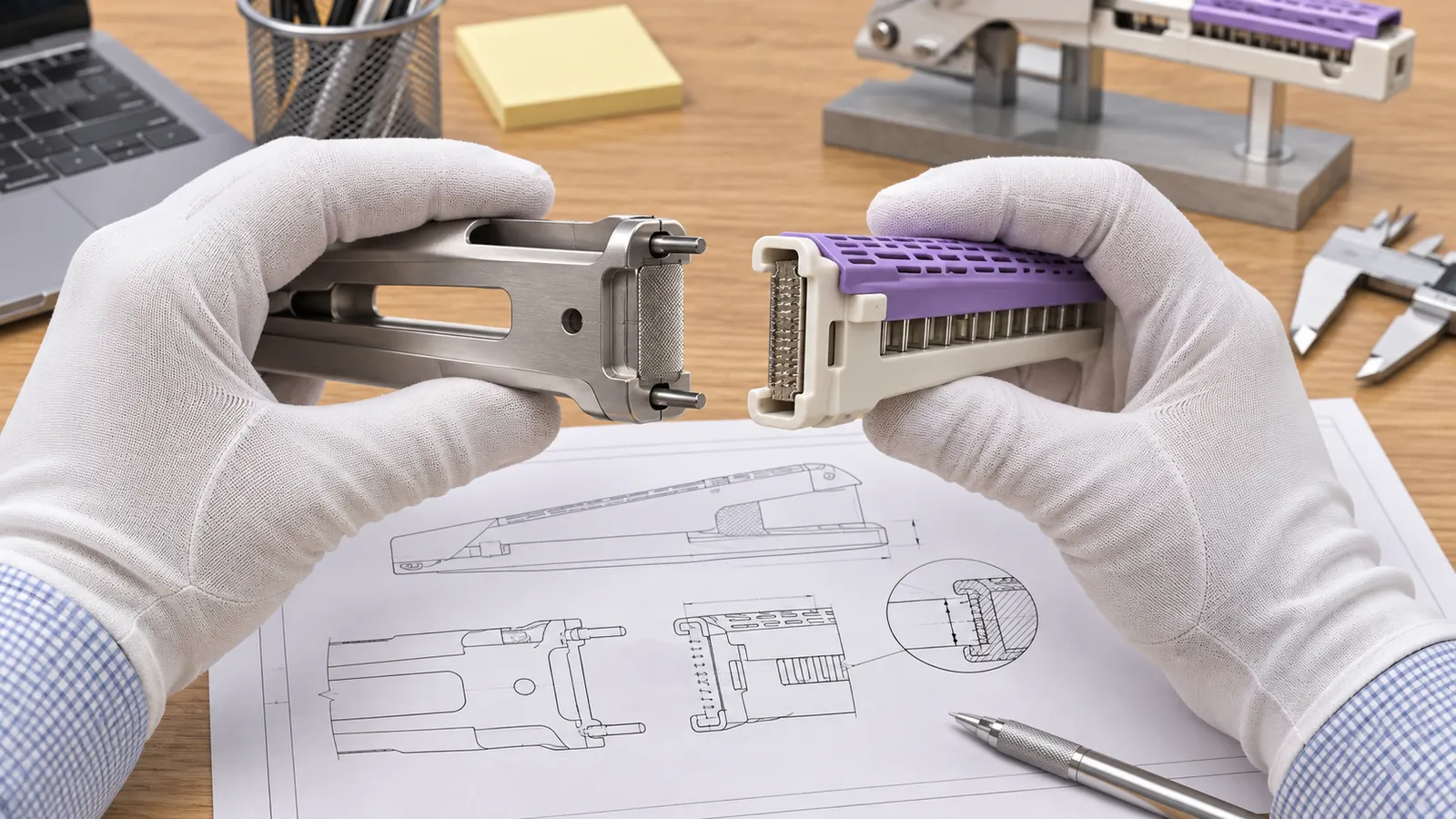
The anvil and cartridge form a paired interface. Staple-forming pockets must relate to the corresponding staple paths, while the anvil’s slot or clearance features must accommodate the instrument’s firing member if the design uses one. Alignment pins, rails, pivots, or other features may control closure. The actual arrangement varies by instrument type, so the component drawing and controlled assembly model are the authority.
Begin the design review with the assembly datums: the pivot or shaft axis, jaw reference plane, closure stop, and any locating features that control lateral or angular position. Then identify which surface or feature controls the anvil face relative to the cartridge. If two anvil sections are joined, define how they are aligned during joining and which features are inspected afterward. A patent may illustrate one architecture, but it should not be treated as the specification for another device.
For related medical component context, the site’s bone saw blade and drive-hub interface guide discusses how an instrument component’s drive interface affects the manufacturing plan. The anvil has a different function, but both examples benefit from defining the mating assembly and datum system before choosing an inspection method.
Small pocket geometry can create large inspection questions
Staple-forming pockets may be small, repeated, and arranged along a curved or straight working surface. A drawing should define their count, pattern, orientation, profile, and relationship to a datum frame. It should also clarify whether the pocket dimensions are inspected individually, by pattern position, or through an agreed functional or optical method. “Match the cartridge” is not a measurable acceptance criterion unless the cartridge interface and test method are specified.
Edge condition matters where burrs or raised material could interfere with assembly or surface requirements. The drawing should state any required edge break or burr limit on functional features rather than relying on an undefined deburring convention. If a slot, pocket, or thin wall is inspected optically, specify the viewing orientation and datum alignment so different operators do not report different values from different setups.
Surface finish requirements should be tied to a function or document. A blanket finish callout may be unnecessary or may obscure the surfaces that actually need control. If a working face has a specified texture, coating, or passivation requirement, state whether dimensions are accepted before or after finishing and how the finish is verified.
Choose a process sequence that protects alignment
Possible routes can include stamping, forming, machining, coining, joining, or a combination, depending on material, geometry, volume, and device design. This is not a claim that every route is available for every part. For early prototypes, subtractive machining may help evaluate accessible geometry, while high-volume designs may use a different near-net process. The chosen route must preserve the pocket pattern, jaw alignment, wall thickness, and joining interfaces required by the released drawing.
Sequence decisions matter. If a blank is formed first, springback or local distortion may influence the final face. If machining happens before joining, the joining operation can shift critical features. If the joint itself establishes the final assembly geometry, the fixture and post-join inspection plan must reflect that. A supplier and buyer should identify which datum features are stable before and after each process step.
Workholding should avoid marking or bending the thin working region. Where a part is long or flexible, support points and clamp force can affect free-state geometry. The drawing should clarify whether acceptance occurs in a relaxed free state or under a defined fixture condition. An inspection result without setup context may be impossible to compare with another supplier’s result.
Define material and cleanliness requirements without guessing
The material grade and condition come from the device design and applicable product requirements. Stainless steels are common in many instrument components, but that general observation does not identify the alloy, heat treatment, surface state, or biocompatibility basis for a particular anvil. The drawing or controlled material specification must name the required grade and documentation. A supplier should not substitute a similar-sounding material or claim medical suitability from a generic grade label.
Cleaning, passivation, sterilization compatibility, packaging, and traceability are product-level requirements that must be supplied by the customer or design authority. They cannot be inferred from the word “surgical.” If a machined prototype is intended only for dimensional evaluation, label its intended status and do not imply that it is validated for clinical use. The buyer should state whether the part is for fit assessment, bench testing, design verification, or another controlled purpose.
For prototype geometry that is compatible with subtractive production, the site’s CNC machining overview provides general process context. The chosen material, device requirements, tolerances, inspection records, and any quality-system obligations still need project-specific review. No certification or regulatory status is implied by a process description.
Build an inspection plan around the real assembly datums
A useful plan separates dimensional characteristics from functional assembly checks. Dimensional inspection can report pocket width, depth, spacing, face flatness, slot position, and alignment features when they are defined. A controlled fixture or mating component may be used for a functional check only when its revision and acceptance criteria are documented. A successful fit in an uncontrolled sample assembly does not prove conformance to the released specification.

- Confirm the drawing revision and the intended prototype or production status.
- Identify the primary jaw datum, pivot axis, and cartridge reference.
- Specify how the pocket pattern and slot position are measured.
- State the condition in which flatness or alignment is accepted.
- Define material, finish, cleaning, traceability, and packaging evidence where required.
- Keep supplier dimensional reports separate from device-level validation conclusions.
For a surgical stapler anvil, optical measurement can be useful for small repeated features, while a CMM or dedicated fixture may suit other geometric relationships. The method should be selected from the drawing characteristics and uncertainty needs. If a feature is inaccessible after joining, measure it earlier in the sequence and define how the subsequent operation is controlled.
Questions for a drawing review
Can a supplier decide the anvil pocket dimensions from a patent?
No. Patents describe particular disclosed embodiments, not the controlled dimensions or acceptance limits of a customer’s device.
Does a dimensional report prove clinical performance?
No. It records specified part characteristics. Device-level performance, safety, sterilization, and regulatory decisions belong to the responsible design and validation program.
What should be provided before a prototype quote?
The released drawing, material specification, assembly interfaces, critical feature list, inspection requirements, prototype purpose, and any finish or documentation requirements.
Conclusion
A well-defined surgical stapler anvil links its working pockets, slot, jaw alignment, and attachment features to the actual cartridge and pivot datums. Clear material and inspection requirements keep prototype evidence bounded to what was measured. That approach helps teams discuss manufacturability and fit without confusing a component sample with a validated medical device.
References
- Surgical anvil arrangements, European patent application.
- Integrated tissue positioning and jaw alignment features for surgical stapler, European patent application.

