


An aircraft wing rib helps define the wing section and transfers loads between the skin, spars, and local attachments. Its manufacturing route depends on whether the design uses a formed sheet, a machined plate or billet, a built-up assembly, or an additive route for a development article. The best choice is the one that preserves the specified interfaces and makes the required features inspectable, not simply the one with the fewest operations.
Ribs can look like flat profiles in a drawing, but manufacturing choices are governed by bends, flanges, cutouts, edge distance, hole position, and how the rib connects to neighboring structure. This article explains the practical questions to settle before a prototype or production RFQ.
Contents
- Read the rib as part of a wing assembly
- Three manufacturing routes, three different tradeoffs
- Protect holes, flanges, and edge distance
- Fixtures should support the inspection plan
- Use prototypes to answer a defined question
- A better RFQ starts with a controlled drawing package
- Frequently asked questions
Read the rib as part of a wing assembly
A rib’s outer contour may set an airfoil-related boundary, while its flanges, lightening cutouts, and holes establish how it attaches to skins, spars, or brackets. Those features have different roles. A visual contour may permit some process allowance, while a hole pattern can control assembly alignment. Manufacturing planning should identify which surfaces are locating features and which are secondary boundaries.
Before releasing a part, compare the rib drawing with the mating-part model or interface drawing. A hole that appears centered on the rib may be dimensioned from a spar datum. A flange angle may depend on a skin contour or bend allowance. If the supplier receives only a flat pattern without the assembly context, the part can be cut accurately and still fail to fit the intended stack-up.
That relationship belongs within the wider Aviation and Aerospace parts manufacturing scope, where prototype choices should be tied to their intended use and the controlled engineering definition.
Three manufacturing routes, three different tradeoffs
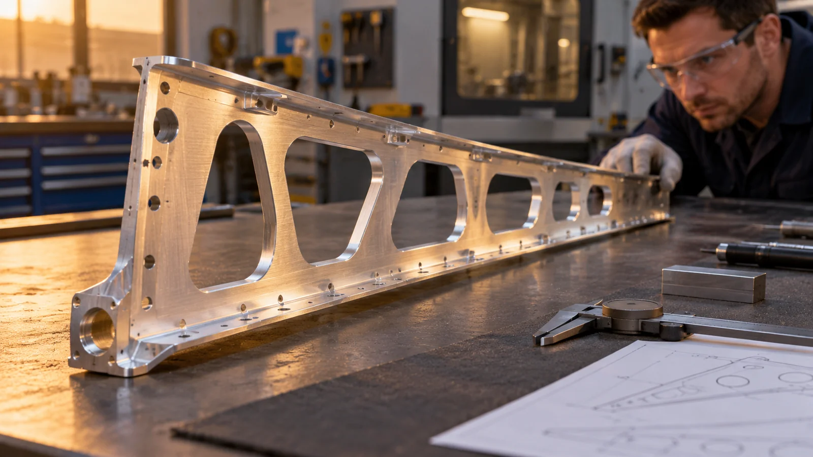
There is no universal process for every rib. Formed sheet can suit a design built around bends and formed flanges. CNC machining from plate can make sense for a one-off geometry or when the drawing defines machined surfaces and pockets. Metal additive manufacturing may support complex development geometries, but it brings its own build orientation, support-removal, post-processing, and inspection decisions. These routes are not interchangeable without engineering review.
| Route | Potential advantage | Questions to resolve |
|---|---|---|
| Formed sheet | Can create flanges and a thin profile with limited material removal | Are bend radii, reliefs, springback, and grain direction defined? |
| CNC-machined blank | Supports complex cutouts and controlled local features | Will thin webs move as surrounding stock is removed? |
| Metal additive route | Can produce geometry that is difficult to form or assemble conventionally | Are build orientation, supports, finishing allowance, and qualification boundaries agreed? |
For sheet-based designs, the sheet metal fabrication service is the relevant process path to review. A model or prototype made by another process can help test fit, but it should not be treated as evidence that the final material and route have been qualified.
When the exact route is not fixed, ask for a process comparison against the same drawing revision and quantity. Compare setup effort, likely rework points, inspection access, and what must change if the geometry is revised. A quote that lists only a unit price hides the reason one route may be more suitable than another.
Protect holes, flanges, and edge distance
Hole patterns should be evaluated from their functional datum, not by measuring each opening from the nearest edge. This matters where a rib attaches to a spar, skin, bracket, or neighboring structure. A small coordinate shift can accumulate across a row or create mismatch when the assembled wing references another datum system.
For formed ribs, bend sequence can influence access to holes and the final location of flanges. A feature that is easy to drill while the blank is flat may become difficult to locate after forming. For machined ribs, remaining material around the hole and cutout may lose stiffness late in the operation sequence. The process plan should preserve enough support until the controlling features are finished.
Edge distance is not an aesthetic margin. It is a drawing-defined relationship that can affect fastener fit and structural intent. The manufacturer should not move a hole to make machining easier without approved design disposition. If tool access or distortion creates a conflict, flag it before cutting and ask for a controlled resolution.
Fixtures should support the inspection plan
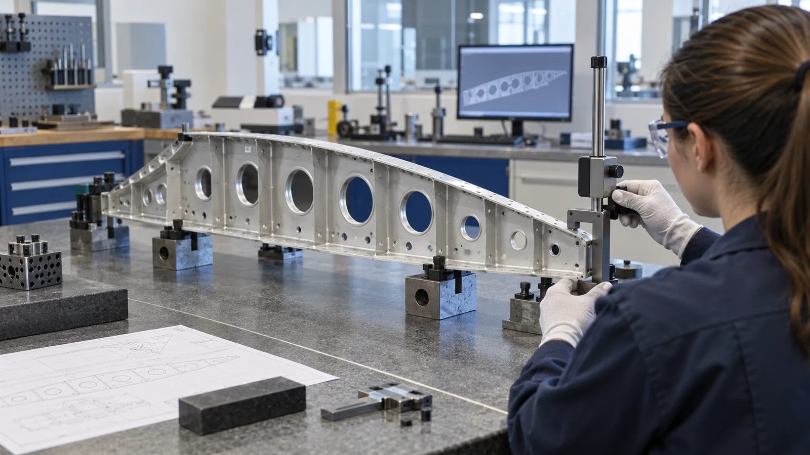
A fixture needs to hold the rib without distorting it and allow the features that matter to be reached by tools and measuring devices. For a formed sheet part, a checking fixture may help verify profile and hole location, but it should reference the same datums as the drawing. For a machined blank, a nest or soft jaw can support thin regions as stock is removed, provided the clamping method does not force the part into a false shape.
Inspection should be planned around characteristic type. Profile, hole position, bend angle, and local flatness may require different measurement approaches. A coordinate measuring machine, pin gauges, height measurement, or a dedicated fixture can each be appropriate depending on the drawing and tolerance. The tool choice should be recorded rather than assumed from the process name.
When a surface will be hidden after assembly, decide whether it needs an in-process check, a pre-assembly record, or another agreed method. Measurement after the feature becomes inaccessible may be impossible.
Use prototypes to answer a defined question
A prototype is useful when the team knows what uncertainty it is meant to reduce. A low-cost fit sample may confirm that a rib clears adjacent parts. A material-specific sample may help study forming response. A machined article may reveal whether thin sections can be supported and inspected. A printed rib may be a geometry mock-up, but it does not automatically represent the final manufacturing material or structural behavior.
For early geometry checks, an aerospace 3D printing route can be considered where the application and validation goal support it. State whether the article is for visual review, fit, assembly sequence, or another defined evaluation. Keep design approval and flight-use qualification outside the supplier’s assumed scope unless the program explicitly assigns them.
A better RFQ starts with a controlled drawing package
Send the current drawing and model revision, material and condition, quantity, finish, critical characteristics, inspection requirements, and any program documentation requirements. Identify the mating interfaces and explain the prototype purpose. If a flat pattern and formed model both exist, state which definition controls and how discrepancies should be handled.
Ask the supplier to identify assumptions about bend sequence, machining allowance, fixture design, and inaccessible measurements. A short, written list of assumptions is easier to review than a quote that silently interprets ambiguous geometry.
Before approving the first article, compare the actual results with the same revision used for the quote. If a design change occurs, distinguish the effect on material, tooling, inspection, and delivery planning rather than treating the change as a simple file replacement.
Frequently asked questions
Are aircraft wing ribs always formed from sheet metal?
No. Some designs use formed sheet, while others may use machined, built-up, composite, or additive approaches. The drawing, aircraft design, quantity, and program requirements determine the route.
Can a 3D-printed rib replace a machined or formed rib?
Only if the responsible design and qualification process approves that material and process for the intended use. A printed fit model can answer geometry questions without establishing production equivalence.
What usually causes a rib to miss its assembly fit?
Common planning issues include mismatched datum references, bend allowance assumptions, hole-pattern transfer, springback, and a prototype built to a different revision than its mating parts.
What information should be marked as critical on the RFQ?
Call out the controlling interfaces, datum scheme, material condition, tolerances, inspection expectations, finish, quantity, and prototype purpose. Keep the drawing or model revision explicit.
A wing rib should be selected and manufactured as an assembly interface, not merely as a cut profile. When the buyer defines the functional datums and prototype purpose early, the supplier can compare forming, machining, and additive options without blurring the boundary between manufacturing evidence and design approval.

