


A brake booster housing is not just a shell around a diaphragm. Its mounting face, pushrod axis, bore or seal lands, and port locations establish how the booster interfaces with the vehicle and the rest of the braking system. If those features drift relative to one another, a visually acceptable casting can still create assembly difficulty or an unreliable interface. The manufacturing plan should therefore begin with functional datums and the drawing, not with a generic assumption that every housing is made the same way.
For a prototype, replacement geometry, or a production transition, automotive brake booster housing machining is best treated as a datum-transfer problem: how will the chosen blank be located, which features will be finished in a common setup, and what inspection evidence will show that the interfaces remain related?
Contents
- Which housing features control fit?
- How material and blank choice affect the route
- Building a machining sequence around datums
- Inspection checks that answer useful questions
- What to provide when requesting a prototype
- Frequently asked questions
Which housing features control fit?
Start by separating functional interfaces from exterior shape. Depending on the design, the housing may include a booster-to-firewall mounting pattern, a master-cylinder interface, vacuum or pressure connections, a diaphragm cavity, a pushrod guide, and sealing surfaces. Not every design uses the same architecture, so the released drawing and model must govern. The important manufacturing task is to understand how each interface is located relative to the others.
A useful datum sche
me often begins with the mounting face or another assembly plane, then uses a bore, pilot, or controlled centerline to establish orientation. Hole patterns, ports, and sealing lands can then be inspected against that reference. If the drawing instead defines a different primary datum, follow it; do not silently replace the designer’s scheme with a shop-preferred coordinate system.
Wall thickness and internal transitions matter as well. Thin ribs, deep cavities, and irregular cast surfaces may respond differently to clamping force and material removal. A housing can meet individual dimensions while still showing distortion after unclamping if the part was not supported appropriately. This is why fixture contact points and machining order deserve review alongside tool access.
How do material and blank choice change the route?
Blank selection depends on design maturity, required quantity, geometry, and the properties specified by engineering. For a small prototype run, machining from stock or from a near-net blank may reduce dedicated tooling. A cast blank can become attractive when the design needs internal contours or when planned volume justifies the casting route, but it introduces its own decisions: draft, parting lines, stock allowance, local porosity risk, and the location of machining datums.
Aluminum is used in some housing designs where the specified strength, mass, and corrosion requirements support it; other designs use different materials. Do not substitute a material based on a generic application description. Confirm the grade, temper or condition, material certification expectations, and any process-specific requirements with the drawing owner. If aluminum is selected, review the available CNC aluminum material options against the actual design requirements rather than treating alloy names as interchangeable.
For a cast route, the die-casting capability may be relevant to evaluating a near-net shape, after which critical interfaces can be finish-machined. The fit bet
ween casting and machining plans should be settled early: machining allowances, datum pads, and inspection access need to be designed into the blank. At low quantities, a different prototype route may be more practical than committing to a production-intent tool.
How should the machining sequence protect datums?
One robust sequence is to create a stable reference surface first, establish the primary bore or pilot from that surface, then finish related interfaces while preserving a repeatable locating scheme. The exact order is part-specific. If multiple faces need to remain square or coaxial, consider whether they can be machined in one setup or whether a qualified transfer datum is needed between operations.
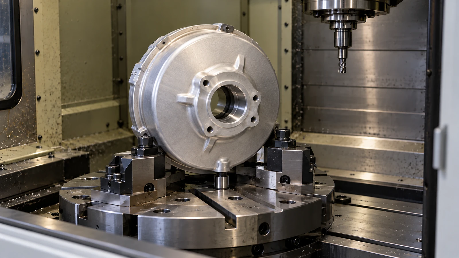
Clamping should support the part without forcing a flexible wall into an artificial shape. Excessive force may make the feature appear correct while clamped and allow it to move when released. Conversely, insufficient support can invite chatter or vibration. A prototype review can include fixture contact strategy, cutting access, expected stock removal, burr control, and how the part will be handled between operations.
Machining allowances should account for the actual blank, not an assumed ideal casting. If the blank is variable, establish inspection gates before removing the material that would expose a defect or leave too little stock at a critical land. Where a design change shifts a port or mounting feature, update the setup plan and inspection references together rather than editing only a toolpath.
Which inspection checks are most informative?
Inspection should answer whether the interfaces meet the drawing and assemble as intended. Depending on specified characteristics, this may include mounting-face flatness, hole position, bore diameter, perpendicularity or coaxial relationships, sealing-land condition, and port location. Use the drawing’s tolerances and datum references; a generic checklist cannot supply acceptance limits.
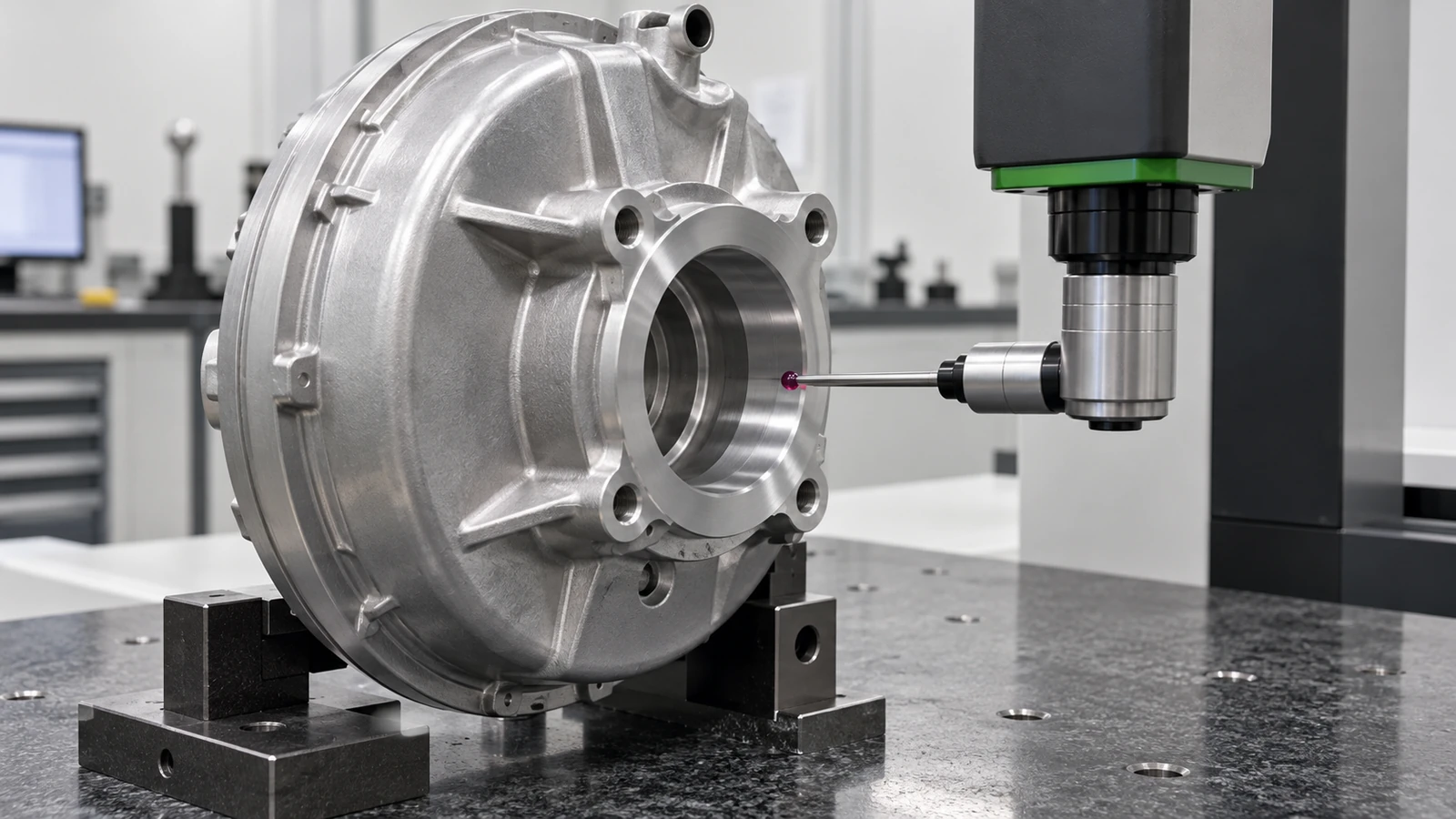
Coordinate measurement can help evaluate positional relationships, while suitable gauges may provide a faster check for repeated features once validated. Surface finish shou
ld be measured only where the drawing calls it out and with a method appropriate to that requirement. Visual review can identify obvious damage or burrs but is not a substitute for dimensional evidence.
For a prototype, agree on the inspection report scope before manufacturing. A focused report tied to critical features is more useful than an unstructured list of readings. If the part is being evaluated for a new design, record the revision, material, process route, and any deviations so engineering can separate design issues from manufacturing variation.
What should a prototype RFQ include?
Send the latest drawing and 3D model, revision, material and condition, quantity, target delivery window, finish requirements, and any characteristics that need inspection evidence. State whether the geometry is for fit checking, functional evaluation, or a production-intent build. These purposes can lead to different blank choices and levels of documentation.
Also identify interfaces that are still under review. For example, if the mounting pattern is fixed but the port geometry is provisional, mark that clearly. Ask the supplier to flag inaccessible features, uncertain stock allowance, or a datum strategy that may affect inspection. Early discussion is especially useful when a design crosses a process boundary from machined prototype to cast production part.
Teams developing multiple vehicle components can use the automotive prototyping overview to understand the broader development context. For a housing-specific plan, keep the discussion anchored to this part’s interfaces, revision, and intended test.
Frequently asked questions
Can every brake booster housing be made from aluminum?
No. Material depends on the design, performance requirements, environment, and released specification. Confirm the exact grade and condition with engineering; do not infer a substitution from the part name.
Should the prototype use the production casting process?
Not automatically. A low-volume prototype may use a machined or alternative n
ear-net blank if it answers the intended design question. Use production-intent casting when the evaluation specifically depends on casting-related structure, process variation, or geometry.
What causes a housing to fail assembly despite acceptable individual dimensions?
Possible causes include datum relationships, accumulated positional variation, clamping distortion, burrs, or an unclear interface definition. Review the drawing’s datum scheme and inspect the assembled relationships, not only isolated dimensions.
What should be checked first in a drawing review?
Confirm the mounting interface, centerline or locating bore, seals, ports, material, critical tolerances, and revision. These define the manufacturing and inspection conversation.

