


When a multichannel pipette block is made, the challenge is not simply producing a row of holes. Each channel must relate to the others, and the completed block must interface with seals, tips, manifolds, or other components defined by the instrument design. A block can look precise yet create uneven fit if bore position, depth, surface condition, or face geometry varies across the array.
That is why multichannel pipette block machining should be planned from the channel pattern outward. First establish what the drawing treats as the locating face and reference axes; next decide how to hold the stock without distortion; then choose a probing and inspection strategy that can evaluate the entire pattern rather than one convenient bore.
Contents
- Why a channel array needs pattern-level control
- Material and blank decisions for a pipette block
- How to machine repeated channels consistently
- Inspecting the full array instead of one bore
- Information to include in a prototype request
- Frequently asked questions
Why is a channel array different from a single bore?
A single bore is usually evaluated by its own size, depth, and axis relative to a datum. In a multichannel block, the pattern adds relationships between features: pitch from channel to channel, row alignment, symmetry about a center plane, and the position of the complete array relative to a mounting face or connector. These relationships may affect how a mating component seats or how seals line up. The required limits must come from the instrument design; they should not be guessed from a generic pipette description.
Repeated features also amplify process variation. If each bo
re is produced with a small but consistent offset, the first position may look acceptable while the end of a long row accumulates displacement. If tool deflection, thermal change, or workholding shifts during the cycle, the pattern may show a trend rather than random scatter. A useful process plan considers the whole field and records where each feature sits within it.
Before programming, clarify whether bores are through, blind, stepped, counterbored, or intersected by cross passages. Check the drawing for sealing lands, threads, reamed sections, edge breaks, and finish requirements. A CAD model can communicate shape, but the drawing defines the accepted dimensions and tolerances unless the engineering team states otherwise.
How should material and stock be selected?
Material choice depends on the block’s function, fluid or cleaning exposure, required stiffness, weight, dimensional stability, and instrument-level validation. Some designs may use a metal block; others may call for an engineering polymer or a combination of materials. Confirm exact grade, temper or condition, and any traceability requirements. Do not substitute a material based only on machinability or a broad claim about chemical compatibility.
For an aluminum design, stock form and grain direction can influence how the part behaves during machining, particularly if the block has thin sections or asymmetric material removal. Review the available CNC aluminum material information alongside the drawing and the intended test. Where a polymer is specified, verify the exact resin and its dimensional and environmental requirements before programming.
For early evaluation, a machined blank can make sense when the goal is to test layout, assembly, or access without committing to production tooling. The broader medical device manufacturing process overview helps place the part among the possible routes, but it does not replace a product-specific risk or regulatory assessment. A prototype component alone
cannot establish instrument performance or compliance.
What machining sequence helps keep channels aligned?
Begin with a stock preparation plan that creates a stable base and locates the intended reference face. If the design uses multiple faces, decide which one is primary and how the part will be re-located for subsequent operations. The goal is not to minimize setup count at any cost; it is to keep the channel axes and mating features tied to a repeatable reference.
For a row or grid of repeated holes, a programmed coordinate pattern can reduce operator-to-operator variability, but it does not remove the need to validate the origin, work offset, tool condition, and fixture stability. A probing routine may help confirm the workpiece location if the equipment and process support it. Record the approach so the setup can be repeated after a tool change or a new batch of stock.
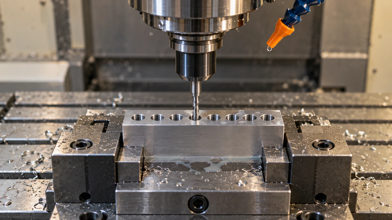
Chip evacuation is important in deep or blind features. Chips trapped at the bottom can affect depth, tool loading, or surface condition. Tool selection, pecking strategy, coolant delivery, and cleaning should be chosen for the specific material and geometry rather than copied from a generic cycle. After machining, deburr without rounding a sealing edge or changing the specified entrance geometry. If the block includes small passages, make sure cleaning and verification methods reach them.
Workholding should support the part without compressing thin walls or bowing the base. If a feature is machined while the workpiece is distorted, it may move after release. For a prototype, it is useful to review clamp locations and the sequence of roughing and finishing before the first cut, especially when material is removed unevenly from both sides.
How can inspection verify the pattern?
Inspection starts with the drawing’s datum system. Measure bore size, depth, position, and orientation where specified, then evaluate the complete channel pattern against its basic dimensions and position tolerances. A single plug gauge can help check a diameter, but it cannot confirm the location of every channel relative to the block’s mounting features.
De
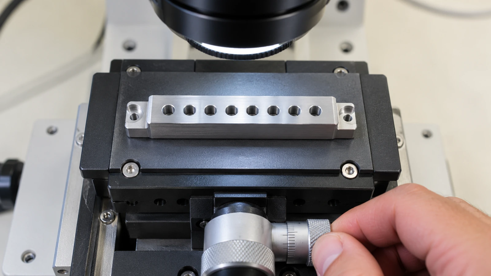
pending on the feature size and accessibility, inspection may use a coordinate measuring machine, optical measurement, a calibrated fixture, pin gauges, or a combination. The method should be capable of resolving the required tolerance and should avoid introducing alignment errors of its own. If the pattern has many channels, define whether every position is measured or whether a justified sampling plan is used; do not silently treat one measured channel as proof of the array.
Surface finish and edge conditions matter where they contact seals or mating parts. Measure finish only where specified, and inspect for burrs, scratches, blocked passages, or residual chips using an agreed method. A useful report identifies the part revision, material, measured features, equipment or method, and any exceptions. It should make a design review easier, not merely produce a collection of numbers.
What belongs in the RFQ and prototype review?
Provide the drawing and 3D model, revision, material and condition, quantity, finish, target schedule, and any required inspection report. Mark the reference face and critical channel relationships if the drawing does not make them easy to interpret. State whether the part is for layout review, fit checking, process evaluation, or another defined purpose.
Clarify whether channels must be cleaned, capped, or protected for delivery, and how the receiving team will inspect them. If the part has fluid-contact surfaces, share the actual cleanliness, passivation, or packaging requirements only when they are specified by the product team. Avoid asking a machine shop to infer intended-use controls from the component name.
For the production route, it can help to compare a CNC-machined prototype with later manufacturing options as design maturity and volume change. The site’s CNC machining service page is a starting point for discussing machined geometry; the final route should still be selected using the approved drawing, material, quantity, and validation plan.
Frequently asked questions
Is one bore measurement enough to ap
prove a multichannel block?
No. It may confirm one diameter, but it does not establish the position, pitch, alignment, or depth of the other channels. Inspection should cover the pattern characteristics specified on the drawing.
Can the channel pattern be copied from a sample part?
A sample can be a reference, but it may include wear, prior modifications, or manufacturing variation. Use a controlled drawing or approved model for acceptance and document how the sample informed the design.
Does CNC machining make a pipette block sterile or clinically validated?
No. Machining describes how geometry is produced. Cleaning, sterilization, biocompatibility, instrument performance, and regulatory validation are separate requirements defined by the product’s intended use and responsible quality system.
What is the most important early decision?
Agree on the datum scheme and the characteristics that govern the channel pattern. That lets manufacturing, inspection, and design teams discuss the same references before material is cut.

