


- Which interfaces determine a wheel hub’s fit?
- Choose a route from the blank to the functional surfaces
- Keep the datum chain intact between setups
- Separate runout, position, and size checks
- Treat material and finish as part of the interface
- What should the wheel hub RFQ include?
- Frequently asked questions
Which interfaces determine a wheel hub’s fit?
A wheel hub may include a bearing seat, wheel-mounting flange, pilot diameter, bolt holes, a brake-disc interface, and a connection to a shaft or bearing assembly. The exact configuration varies by design. On the drawing, identify which surfaces locate the part during assembly and which features transfer load or establish concentricity. A cosmetic outer profile is not automatically a datum, and an easily measured face is not necessarily the best reference. Ask the design team to mark the primary and secondary datums and show how runout is evaluated. If the bearing axis is the controlling reference, dimensions for the flange, pilot, and bolt pattern should relate back to that axis through a defined datum scheme. This avoids treating each feature as an isolated coordinate. It also helps manufacturing and inspection teams use compatible setups.
Choose a route from the blank to the functional surfaces
Prototype hubs can begin as a machined billet or a near-net-shape blank, depending on geometry, material, quantity, and what the build must prove. A billet can be practical when the design is changing or the sample count is small. A casting or forging may become relevant when geometry and volume justify that blank route, but it introduces its own allowance, material-condition, and distortion questions. The final decision belongs to the project’s cost, schedule, and validation needs.
| Route consideration | What it can help with | What to review |
|---|---|---|
| Machined billet | Design iteration and direct access to defined features | Material waste, stock size, tool access, and machining distortion |
| Near-net blank plus machining | Reducing stock removal when the geometry and volume support it | Allowance, datum creation, blank variation, and inspection before finishing |
| Prototype-only route | Learning about fit before committing to production tooling | Which features must match the later production route and which are provisional |
These are planning categories, not a universal ranking. A route that is economical for one hub may be unsuitable for another because bearing-seat geometry, blank availability, or the validation question differs. If the program is still comparing options, the site’s automotive manufacturing-process overview can help frame the process discussion without replacing part-specific DFM.
Keep the datum chain intact between setups
Many hub features are machined from more than one side. Each time a part is unclamped and repositioned, the setup must preserve its relationship to the chosen reference. A practical plan may rough the stock, establish a stable datum, machine bearing-related features, then finish the flange and mounting pattern in a setup that controls their relationship. The order depends on the blank and design; the drawing should make the critical relationships visible before the sequence is fixed. Thin flanges, interrupted cuts, and asymmetric stock removal can create movement. Balanced stock removal and a planned roughing-to-finishing sequence can reduce the risk that a surface shifts after it has been treated as final. The programmer and machinist also need to account for tool reach, support points, and clamping forces. If a feature is inspected before the part reaches a stable state, a later operation may change the result. Record which dimensions are provisional at each stage.
Separate runout, position, and size checks
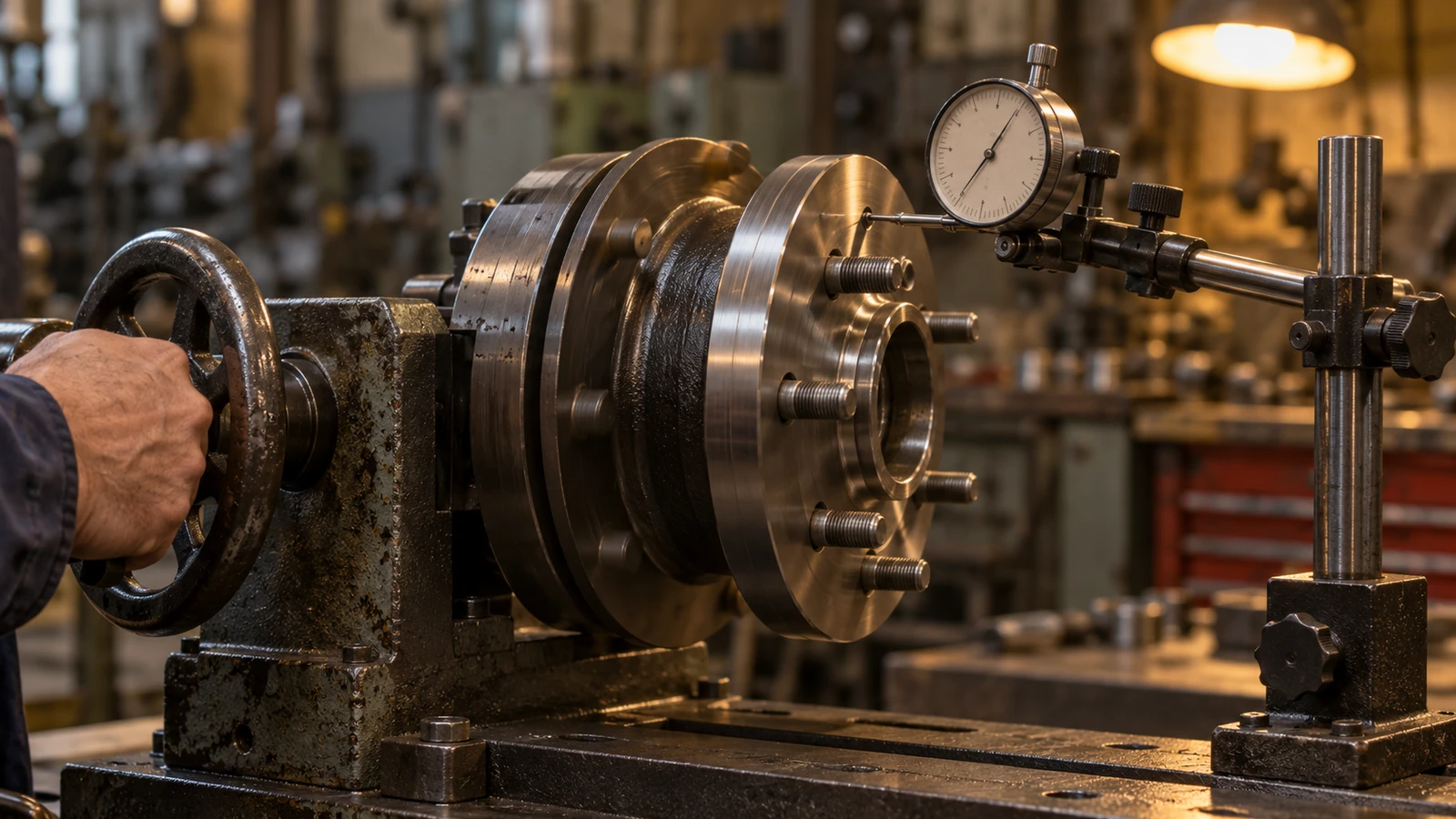
Runout is a relationship measured around a referenced axis; it does not replace checking size, location, or perpendicularity. A bearing seat may be within its diameter limits and still show unacceptable runout relative to the flange. Conversely, a runout measurement alone does not tell whether the bolt holes or pilot diameter are correctly positioned. Build an inspection plan that assigns a method to each drawing requirement.
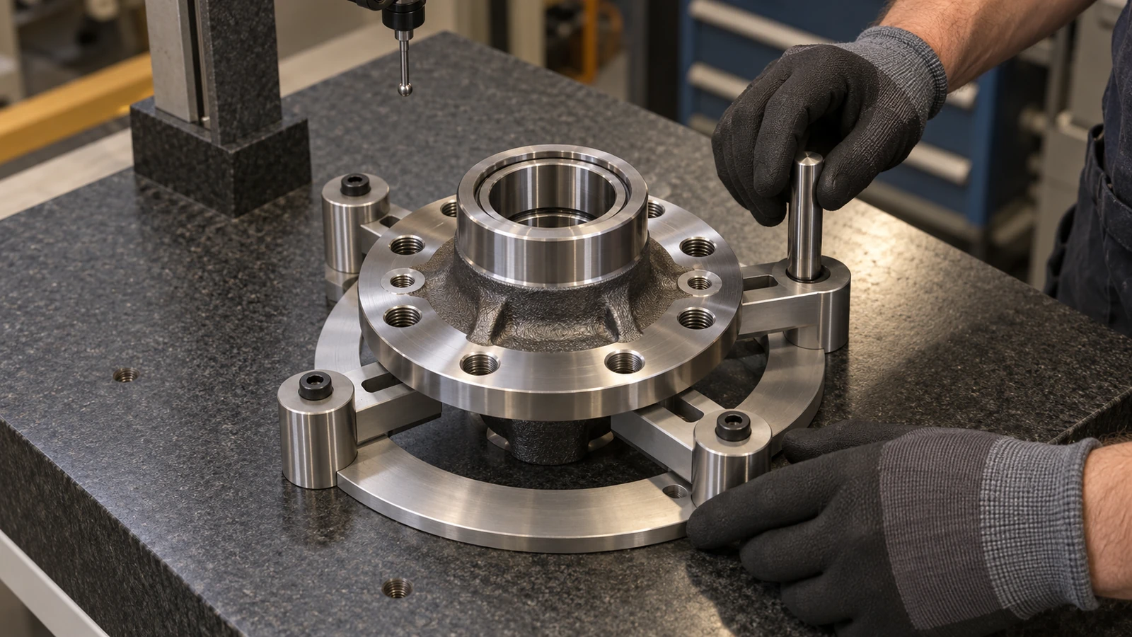
For a small prototype lot, a coordinate measuring machine or suitable dedicated fixture may be selected according to feature geometry and customer requirements. The setup should support the part consistently and avoid clamping it into a shape that disappears after release. Specify the datum alignment, contact points, probe access, and report format when those details matter. A report is useful only when the measured feature and reference frame correspond to the drawing.
Treat material and finish as part of the interface
Material choice affects machinability, strength, mass, corrosion behavior, and the finishing route. It should come from the vehicle program’s requirements and approved material specification, not from a generic claim that one alloy is always best. Confirm alloy, product form, temper or condition, and required records before machining. Where coatings or other finishes are specified, identify which faces are functional, whether dimensions apply before or after finishing, and how protected surfaces will be handled. Do not apply a finish allowance by assumption. Coating buildup, masking, polishing, or corrosion protection can affect fits and measurements. Define the required appearance separately from functional surface requirements. The existing automotive material-selection guide provides broader selection context; the hub drawing and program specification remain controlling.
What should the wheel hub RFQ include?
Send a revision-controlled 3D model and drawing, material and condition, quantity, target build stage, finish requirements, datum scheme, and inspection expectations. Mark the bearing axis, flange, pilot, bolt pattern, and any brake or shaft interfaces that control assembly. If the design is still evolving, identify which features are frozen and which may change. Ask the supplier to flag setup assumptions, blank limitations, inspection access, and any dimensions that need clarification before quotation. For a prototype, also say what the part must help the engineering team learn: assembly fit, runout behavior, brake-stack alignment, or another defined question. A clear purpose helps avoid spending effort on noncritical details while leaving the key interface uncertain.
Frequently asked questions
Can a wheel hub be machined from billet for a prototype?
It can be considered when the design, material, quantity, and validation purpose make direct machining practical. The supplier should review stock size, access, material use, and whether the prototype needs to represent a later blank route.
Is bearing-seat diameter enough to confirm hub quality?
No. The drawing may also control runout, flange relationship, pilot diameter, bolt-hole location, and other interfaces. Inspection should follow the complete datum scheme.
Should dimensions be checked before or after coating?
That depends on the drawing and finishing specification. State when each dimension applies and identify which surfaces must be masked or measured after finishing.