


A trocar is often discussed as a single instrument, yet its manufacturing definition may cover several connected parts: a cannula, an obturator, a seal or valve, a handle, and interfaces that guide assembly. If those elements are reviewed separately, a supplier can meet individual dimensions while missing the relationship that controls fit, movement, or sealing.
Endoscopic trocar manufacturing is therefore an interface-control problem as much as a machining problem. This article focuses on component design, material/process coordination, inspection, and supplier handoff. It does not provide clinical instructions or claim that manufacturing a component establishes device approval, sterility, or validated reprocessing.
Define the assembly before quoting a component
Trocar designs vary. Some are reusable; others are labeled single-use. Component count, geometry, sealing architecture, materials, and downstream assembly all depend on the specific device. A supplier should work from the controlled drawing set and bill of materials, not assume that a generic trocar illustration defines the product.
At the start of a quote, identify whether the request covers the entire device, a machined component, or a subassembly. Confirm the intended revision, quantity, material specification, surface requirements, and inspection deliverables. If the request is for the cannula alone, the interface to the obturator or seal may still determine critical dimensions, but the supplier should not infer requirements that are absent from the drawing.
Separating the part scope also prevents a common communication problem: describing a machined component as if it were a finished medical device. Manufacturing, assembly, cleaning, sterilization, labeling, and regulatory responsibilities may sit with different parties. Name the boundary in the purchase package and state what evidence is expected from each party.
Map the three interfaces that drive fit
A component map makes the assembly easier to review. For each interface, list the mating feature, datum relationship, required clearance or contact condition, and inspection evidence. Keep nominal dimensions, geometric controls, and assembly requirements in their proper roles.
| Interface | Typical manufacturing question | Evidence to define |
|---|---|---|
| Cannula to obturator | Are axis, entry geometry, and sliding relationship defined? | Drawing characteristics, fit check, and any approved functional gauge |
| Cannula to seal or valve | Does the proximal interface locate and retain the seal component? | Seat geometry, surface condition, assembly stack, and inspection method |
| Handle to shaft or assembly | Are orientation, retention, and datum transfer controlled? | Position/orientation callouts, retention requirement, and revision traceability |

These are planning prompts, not universal design requirements. A particular trocar may use a different architecture. The design authority must define the required acceptance condition, especially if a seal depends on a specified compression, surface, or assembly sequence.
Keep the cannula axis and end features related
A cannula can contain a long bore, a distal end feature, and a proximal connection. The bore’s size is only one part of the requirement. Straightness, axis location, end-face relationship, and mating geometry may matter if the drawing controls them. A tube can measure within its diameter tolerance yet be misaligned to an end feature after cutting, joining, or secondary machining.
Plan the sequence so the reference used for the bore and the reference used for the end features remain connected. Depending on the specified construction, the route may involve turning, drilling, reaming, grinding, laser processing, forming, or joining. These are alternative process families, not a claim that each is appropriate for every design. The chosen route must suit the material, geometry, quantity, and drawing.
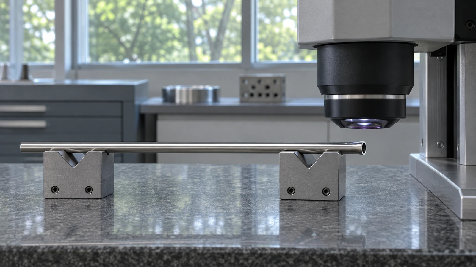
Thin-wall components need controlled support. Clamping can ovalize a tube or alter its measured position. If an end is machined after forming or joining, identify the datum-transfer method and the inspection stage. State whether dimensions apply before or after a coating or other surface treatment. A tolerance should not be interpreted without its drawing references and measurement condition.
Features at the distal end deserve a separate review because they may have a specified shape, edge, or transition. Do not add a generic edge break if the drawing defines a controlled profile. If the edge must be free of burrs, define how it will be reached and verified, especially where the internal bore meets an opening.
Treat the seal region as a controlled interface
Where the design includes a seal or valve, the surrounding seat and mating features should be reviewed together. A seal-related issue may trace back to concentricity, surface condition, a shoulder location, assembly stack, or a component revision mismatch. The exact controls belong to the device drawing and assembly specification.
Specify whether the seal component is customer-supplied, purchased, or included in the machining scope. If a functional fit check is required, provide the approved mating component or gauge and define what that check proves. A physical fit check may answer an assembly question but does not establish every dimensional characteristic or validate a finished device.
Surface requirements must name the relevant area and stage. A seal-contact surface may have a specific finish while an exterior surface uses a general note. If a coating or treatment applies, define masking boundaries and which dimensions are verified afterward. Avoid vague language such as “smooth enough to seal” when a controlled drawing requirement is available.
Separate material choice from finished-device claims
Material selection should follow the released specification. If a drawing names a stainless grade, polymer, or other material, record its exact designation and condition. Do not replace it based on broad labels such as “medical steel” or “medical plastic.” Any alternative needs approval from the responsible design and quality functions.
For polymer or elastomer seal components, material lot, formulation, processing, and post-process behavior may matter to the assembly, but these are not established by machining a neighboring metal part. For metal cannulas and housings, the specified condition and surface treatment need to be stated. The finished-device owner determines applicable material, biocompatibility, sterilization, and regulatory evidence.
Reusable-device design adds a separate cleanability consideration. FDA explains that reusable medical devices require device-specific reprocessing steps and identifies narrow lumens, hinges, sleeves, and adjacent surfaces as features that can create cleaning challenges. This is a design and validation issue for the device manufacturer; it is not proof that a given trocar is reusable or that a machined component meets a cleaning validation. See FDA’s overview of reusable medical-device reprocessing and its notes on design features affecting reprocessing quality.
Inspect the assembly logic, not only loose parts
Inspection planning should match each characteristic to a method. A bore gauge can report bore size at chosen locations; it does not automatically verify axis relationship to a seal seat. Optical inspection can show an accessible edge; it may not reveal a burr deep in a channel. A CMM can evaluate position when the setup and probe access support the required datum scheme.
For a first article, agree on which features are reported, how datums are simulated, and whether measurements occur before or after joining, coating, or assembly. If a subassembly is part of the purchase scope, distinguish component inspection from assembly inspection. Record the drawing revision and component identity so the result can be traced to the actual configuration.
A test fixture or mating part should be controlled. If it is a reference gauge, identify its revision and which interface it checks. Do not let a visual fit check replace a dimensioned inspection report when the drawing requires one. Conversely, do not request a large inspection package that does not answer the program’s actual engineering question.
Jucheng’s related endoscope distal-tip machining article covers a different component at the distal end of an endoscope. A trocar article should retain its assembly focus and can also connect to the site’s surgical instrument tray fabrication discussion where packaging or instrument-set interfaces are relevant.
FAQ
Does every trocar include the same cannula, obturator, and seal arrangement?
No. Designs and configurations vary. Use the current device drawings and bill of materials to define the assembly and supplier scope.
Can a machined cannula be described as a finished or sterile trocar?
No, not based on machining alone. Assembly, cleaning, sterilization, labeling, and regulatory evidence must be defined by the responsible finished-device organization.
What is the key dimensional risk on a long cannula?
The relevant risk depends on the drawing, but size alone may not control the relationship between the bore axis, end features, and mating interfaces. Review the full datum scheme and inspection method.
What should a trocar RFQ include?
Provide the exact component scope, controlled drawings and revision, material specification, quantity, surface and edge conditions, mating references, assembly requirements, and required inspection records.

