


Designing custom hardware mockups often tempts product development teams to specify extreme tolerances and ultra-smooth finishes that have zero impact on functional performance. Every micro-inch of unnecessary precision and every manual polishing hour adds steep premiums to your bottom line, blowing past tight developmental budgets. Sourcing physical validation models requires a balanced manufacturing strategy that matches your immediate validation objectives with the most cost-effective fabrication process. Eliminating over-engineered features early ensures you secure structurally sound parts without overpaying for cosmetic details.
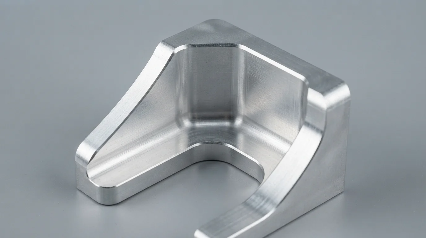
Optimizing your CAD geometries before sending them out for RFQs represents the easiest way to lower total manufacturing expenditures. Manufacturing specialists evaluate tool access directions, internal raw material volumes, and parting line locations using advanced diagnostic software. Resolving thick wall sections, sharp internal corners, and multi-setup profiles during early iterations ensures your files are optimized for fast machine runs. Let’s look at how you can apply practical, shop-floor design-for-manufacturability (DFM) rules to drive down expenses safely.
Table of Contents
1. Process Matching and Bypassing Performance Overkill
2. Subtractive CNC Optimization through Fewer Clamping Setups
Process Matching and Bypassing Performance Overkill
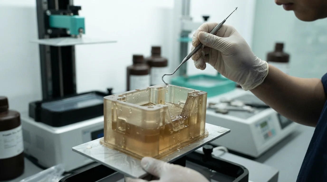
Question: What is the most common cause of high prototyping bills? Specifying high-precision CNC machining for early-stage visual models when low-cost 3D printing or vacuum casting is fully adequate.
Selecting the correct fabrication methodology represents your first line of defense against bloated development invoices. Product teams frequently make the mistake of requesting high-precision CNC machining for early-stage form studies, where high physical strength is completely irrelevant. Utilizing fast, low-cost SLA or SLS printing provides excellent cosmetic and volumetric feedback at a fraction of machining expenses. Learning how to reduce rapid prototyping cost starts with matching your immediate testing phase with the most economical manufacturing process.
Sourcing functional prototypes, however, demands genuine engineering alloys or high-fatigue plastics that must withstand real physical stress. Using FDM plastic filaments for structural load-bearing tests often results in layer-peeling failures, rendering the validation study useless. Engineers specify CNC milling from solid plastic or metal billets only when physical strength, airtight sealing, or environmental thermal limits are mandatory. Bypassing over-engineered requirements on early visual models lets you reallocate funds toward high-precision functional validation trials.
Subtractive CNC Optimization through Fewer Clamping Setups
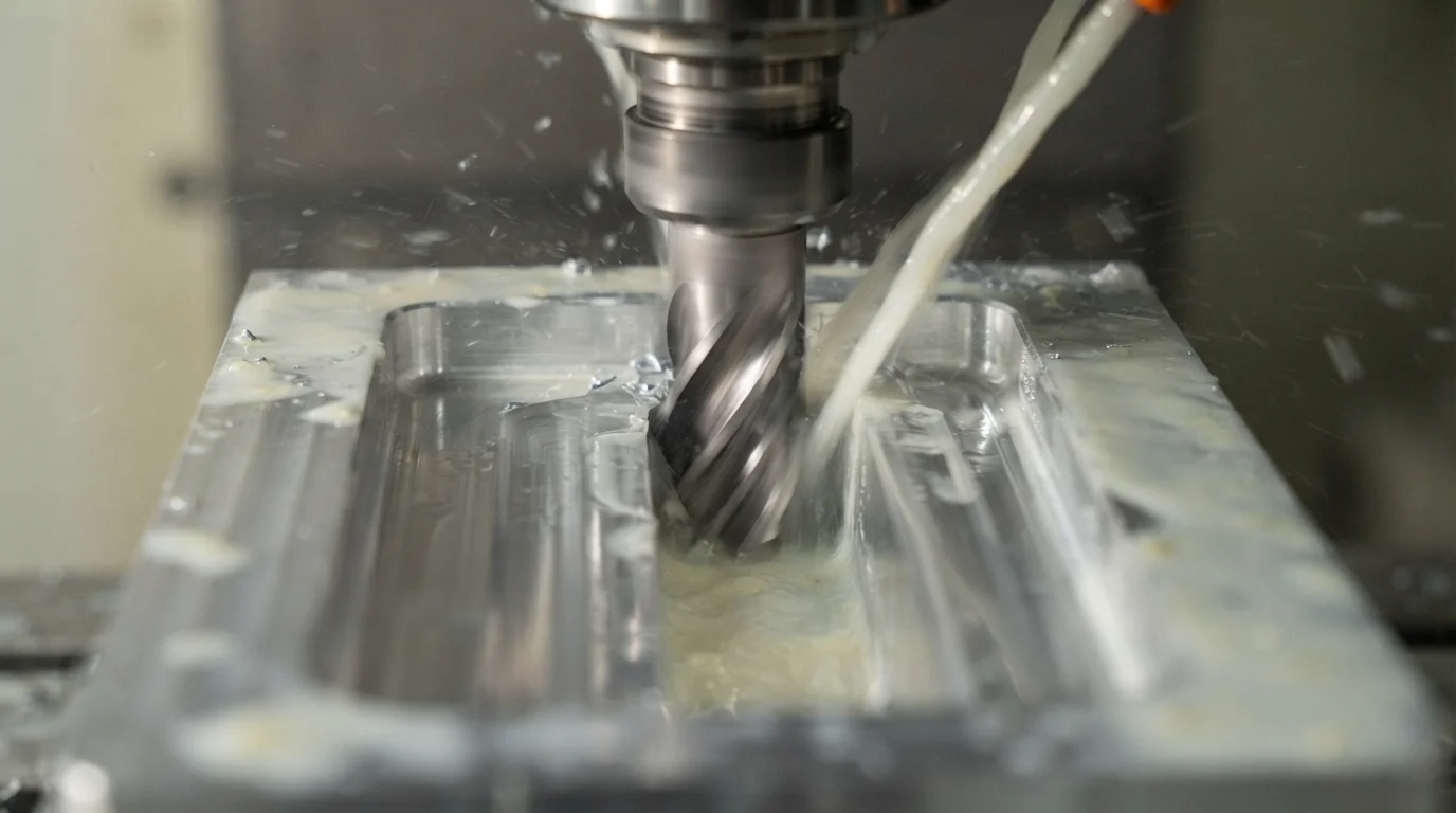
Question: How does setup reduction lower CNC prototyping costs? Aligning machined features along a single coordinate axis minimizes the need for manual part rotations and custom holding fixtures.
Clamping setups represent the primary driver of labor expenses in subtractive manufacturing, as each raw block rotation requires manual alignment. Part designs that feature tapped holes or deep pockets on all six faces demand six separate coordinate setups, inflating machine time charges. Designers must try to concentrate milled features on fewer sides to allow standard vices to hold the workpiece efficiently. Minimizing clamping setups ensures your dimensional tolerances remain highly repeatable while lowering your overall rapid prototyping cost dramatically.
Standardizing internal fillet radii also simplifies CNC milling by allowing standard-diameter endmills to cut internal features quickly. Sharp vertical internal corners are physically impossible for round cutters to carve, requiring slow, expensive secondary EDM processes to resolve. Specifying a minimum internal radius of 1.5 mm allows standard 3.0 mm cutters to slide through deep channels smoothly without tool chatter. Designing corners that match standard metric tool profiles eliminates tool binding risks and prevents expensive tap breakage.
Additive DFM Rules and Hollowing out Plastic Volume
Question: How is 3D printing cost reduced for large parts? Hollowing out solid plastic sections and incorporating escape holes reduces raw material volume and print cycle times.
Polygonal 3D printers calculate part pricing primarily based on raw material volume and total laser exposure time inside build chambers. Solid, thick plastic blocks consume excessive photopolymer resins or nylon powders, increasing raw material expenses unnecessarily. Designing parts with hollow internal cavities and small escape holes allows uncured liquid or powder to drain free easily, reducing part weight. Sizing nominal wall thicknesses to a uniform 1.5 mm to 3.0 mm maintains robust structural stiffness while optimizing print speeds.
Integrating reinforcing ribs within hollowed-out enclosures provides outstanding load-bearing stiffness without adding bulky mass. Sizing internal ribs to 60 percent of the nominal wall thickness prevents shrinkage stresses from causing cosmetic sink marks during subsequent molding transitions. Implementing these smart CAD adjustments is a proven method when studying how to reduce rapid prototyping cost on large-format enclosures. This technical table outlines baseline design changes that directly drive down expenses across different processes:
| Design Variable | Expensive Design Practice | Cost-Saving Alternative | Primary Financial Benefit |
|---|---|---|---|
| Internal Corners | Sharp vertical 90° corners | Rounded radii (≥ 1.5 mm) | Eliminates slow secondary EDM, prevents tool wear |
| Machined Setups | Milled features on all 6 faces | Features concentrated on 1 or 2 faces | Lowers manual setup hours, cuts programming time |
| Wall Thickness | Thick, variable solid blocks | Hollowed walls (1.5 – 3.0 mm) with ribs | Reduces raw polymer volume, accelerates print speeds |
Jucheng Precision operates a fully equipped manufacturing facility containing 150+ CNC machines, including 25 high-precision 5-axis Haas/Mazak machines to mill complex parts. Factory specialists deliver comprehensive 24-hour free DFM analyses to help you optimize geometries, parting lines, and draft profiles before cutting metal. Sourcing your prototypes from our certified facility ensures our experienced engineers suggest practical design tweaks to lower your overall bills. Sourcing fully validated, production-grade components within 4 to 15 days allows mechatronics groups to accelerate development schedules safely.
Operating under a strict no-MOQ policy enables product groups to test customized hardware variations without paying heavy upfront penalties. Specialized rapid tooling molds deliver high-quality injection-molded components within 4 to 15 days, helping design groups transition smoothly from low-volume prototypes to mass production. Sourcing your quotes manually ensures experienced engineers review your CAD files to find additional ways of how to reduce rapid prototyping cost. Partnering with a certified manufacturer ensures your designs transition smoothly from early concept models to mass series production.
Frequently Asked Questions (FAQ)
What is the single most expensive feature in CNC prototyping?
Demanding micro-tolerances down to ±0.01 mm for non-critical features represents the most expensive design oversight in subtractive machining. Loosening non-mating tolerances to ±0.1 mm reduces machine inspection hours and allows faster cutting speeds.
Does complex surface polishing increase prototyping bills dramatically?
Manual hand-polishing and vapor-polishing require intensive labor hours, which can double your overall project bill. Specifying standard bead-blasted or raw machine finishes for internal structures or early visual models lowers your total rapid prototyping cost.
How can mold tooling expenses be reduced for short-run production?
Designing simple parting lines and integrating uniform draft angles eliminates the need for expensive mechanical sliders in rapid molds. Sourcing early DFM reviews ensures your CAD layout is fully optimized before mold core cutting begins.

