


A part can pass dimensional inspection and still puncture a pouch or work loose in a protective tray during transport. Medical device packaging validation therefore cannot be separated from the physical device placed inside the package. Part mass, edge condition, orientation, assembly stability and cleanliness influence how the packaging system performs.
Consider the component manufacturer’s role as an upstream contributor: provide representative hardware and accurate specifications, identify mechanical hazards and maintain the defined release condition. Packaging design, specialized testing and device-level regulatory decisions require their own qualified owners. This article follows an illustrative metal-and-polymer assembly from final inspection to its packaging review; it does not describe a Jucheng customer case.
At Final Inspection: Look Beyond Drawing Dimensions
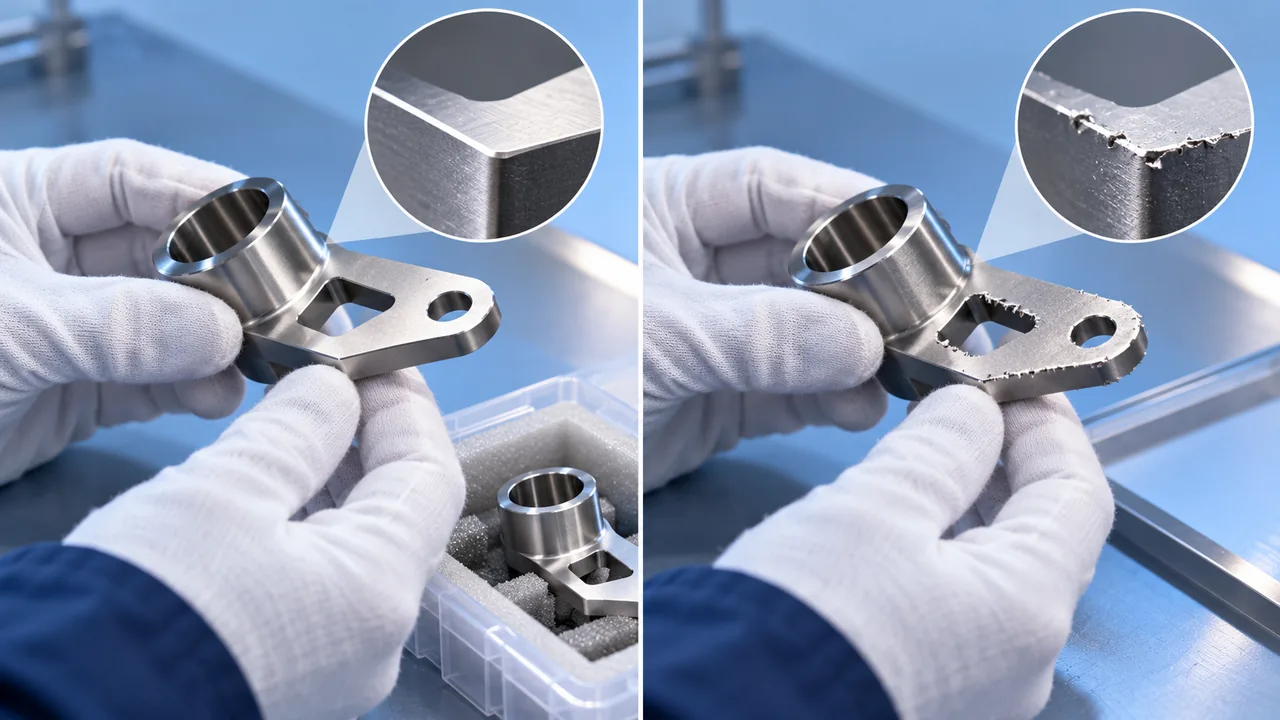
Imagine a handheld diagnostic assembly with a machined metal frame, a molded cover and a small projecting connector. Its dimensions may conform to the drawing, yet the connector can become the first contact point against a pouch. A local burr may be too small to change the measured outline but large enough to create abrasion.
Define edge requirements where contact with the packaging is foreseeable. A general deburr instruction can be ambiguous when a designer wants one edge rounded and another kept sharp for function. Show the relevant surfaces and discuss the permitted edge condition with manufacturing and packaging teams.
Inspect the device in the packaged assembly state. An individually protected component may become unprotected after assembly, or a fastener may protrude when the cover is fitted. Include this configuration in the review rather than relying on photographs of separate finished parts.
Within the medical device manufacturing processes route, identify the last operation that can alter an edge, surface or assembly condition. Packaging checks should occur after that operation, not before a subsequent step introduces a new hazard.
At the Tray: Control Motion Without Distorting the Device
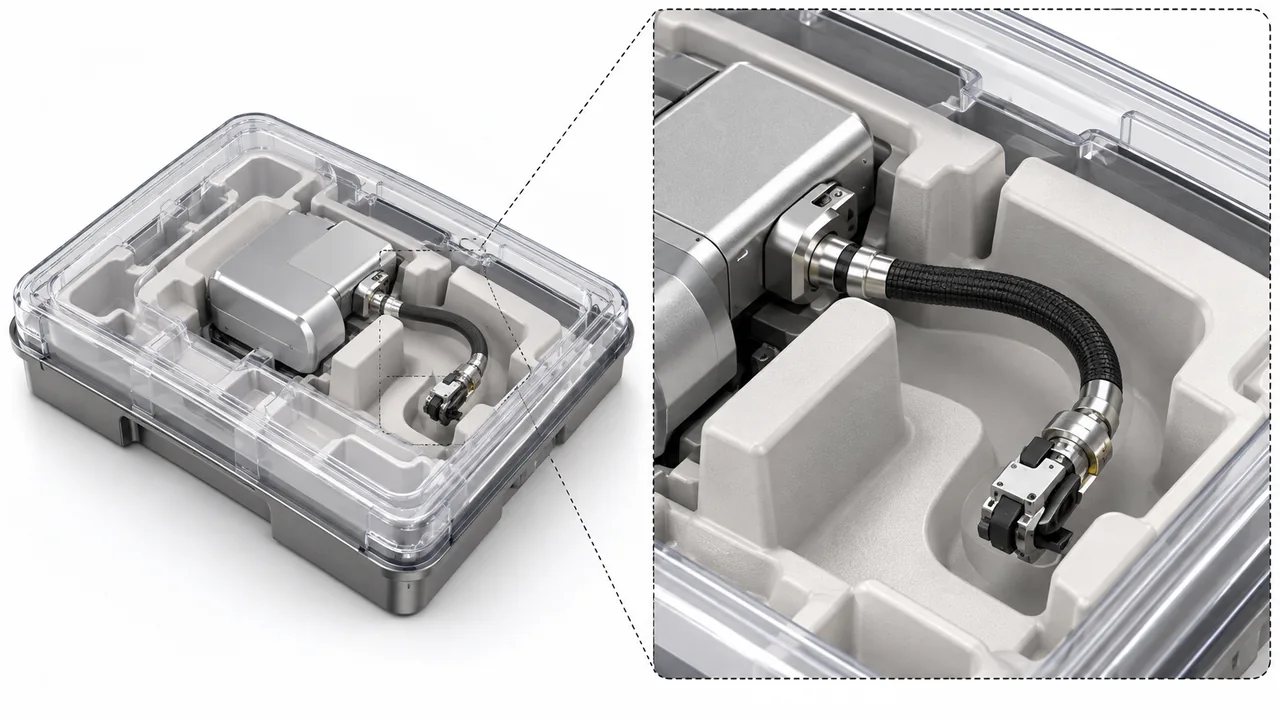
A tray should protect the product, but restraint can create its own problem. A clip pressing on a flexible cover may change an assembly gap. A support placed on a delicate lever may preload a mechanism throughout storage. A highly localized contact under a heavy part may concentrate load during a distribution event.
Map the load path through the restraint. Identify surfaces that can safely carry the device’s mass and surfaces that must remain unloaded. Consider whether the package supports the assembly near its stiff structure or relies on a thin cosmetic panel.
| Physical feature | Potential packaging failure | Useful design discussion |
|---|---|---|
| Projecting connector | Local abrasion or puncture | Orientation, clearance and protective restraint |
| Heavy metal frame | Concentrated impact load | Support area and motion control |
| Flexible molded cover | Persistent deflection in storage | Clip force and contact location |
| Loose accessory | Collision with the main assembly | Separate cavity or controlled retention |
| Textured or sharp surface | Wear against the barrier | Surface requirement and protective interface |
Use prototyping to examine fit, removal and restraint early. A prototype tray or dummy device can answer mechanical layout questions, but it may not establish the final package’s barrier properties or represent the production device’s mass and surface condition.
A Fit Check Is Not a Distribution Evaluation
A device fitting neatly into a tray on a bench proves little about movement during distribution. Review the relevant distribution and handling assumptions with the packaging specialists. They should determine the justified test program and acceptance criteria rather than using a convenient shipping test without a product-specific rationale.
At the Cleanliness Handoff: Preserve the Released State
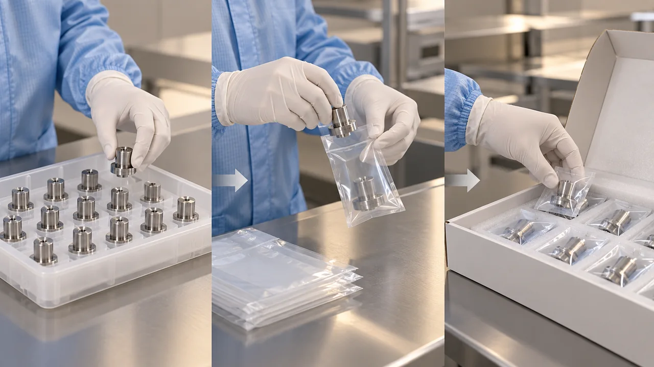
Specify the condition in which parts enter packaging. Protective handling, inspection tools, trays and temporary storage can introduce contamination after a cleaning step. The packaging operator needs to distinguish released clean product from work that still requires processing.
The contact materials used inside a package deserve attention as well. Protective foams, inserts or bags that are adequate for general industrial parts may not be appropriate for a medical device’s defined cleanliness requirements. Selection should reflect the device and packaging strategy rather than a familiar supplier catalog.
Consider marks left by restraint. A surface that is cosmetic during manufacture may become functionally important if the device relies on it for a seal or controlled grip. Do not accept packaging-induced scuffing automatically merely because the part originally passed inspection.
The medical cleanroom manufacturing discussion addresses environmental interfaces. A controlled environment and a validated packaging system answer related but different questions; neither should be used as shorthand for all cleanliness or sterility requirements.
At Validation: Choose Samples That Represent the Challenge
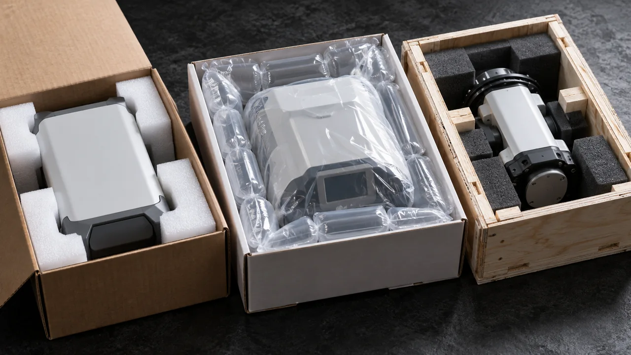
A family of products may share packaging, but the same member may not be worst-case for every endpoint. A heavier variant can create a mechanical challenge, while a sharper or differently shaped variant can challenge local protection. Document why the chosen configuration represents the relevant family.
Nelson Labs’ packaging validation material identifies device characteristics, materials, sterilization and distribution conditions as considerations in worst-case planning. The practical implication for a component supplier is to describe the actual variant differences rather than shipping whichever samples are easiest to obtain.
Samples should include the agreed finishing and assembly state. Substituting a smooth plastic dummy for a heavier metal device may help an early fit review but may underrepresent loads during a later test. Leaving out a sharp accessory can similarly remove the challenge the package needs to withstand.
Keep packaging integrity, seal strength, distribution performance and aging questions distinct in the protocol. Accelerated aging is not a universal substitute for all other evidence, and it should not be presented as automatically proving every shelf-life assumption. Qualified specialists should justify the relevant approach and any ongoing real-time work.
At Release: Make the Device-Package Interface Repeatable
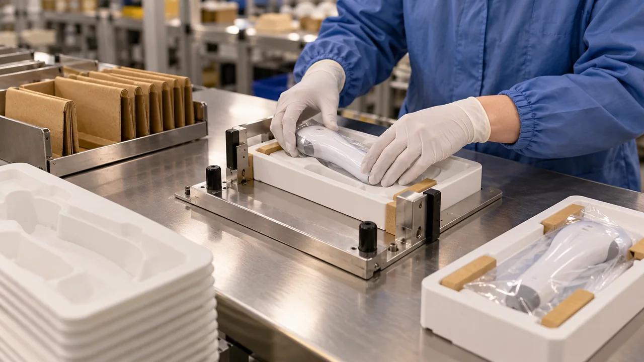
Document the approved orientation, accessory locations, restraint and handling method. If an operator can place the same assembly in several orientations, determine whether all are acceptable. Where only one is correct, make the instruction and physical presentation unambiguous.
Define component characteristics that packaging depends on. They can include edge condition, assembly retention, mass range or a critical contact surface. This turns packaging compatibility into a controlled interface instead of a verbal warning to be careful.
For sheet metal components, review burr direction, formed edges and protruding hardware. A change in bending or fastening can alter contact with a protective package even when the main drawing dimensions remain unchanged.
In a Jucheng manufacturing review, provide the intended presentation, relevant packaging contact areas and final component condition. Confirm the sample quantities and records needed by your packaging partner. This supports representative testing without assuming that machining or molding services include sterile-barrier validation.
What Should Be Rechecked After a Device Change?
Assess the effect of altered dimensions, edges, weight, materials, surface treatment, accessories and assembly state. Even a small connector relocation can change the contact point during transport. The responsible team should decide whether existing evidence remains representative and record the rationale.
Is an Undamaged Box Enough to Accept a Sterile Package?
No. The shipping box and the sterile barrier have different functions. A visually intact outer container does not establish the performance of the barrier or its seals. Use the appropriate, justified evaluations for the packaging system and its intended claim.
Can the Component Supplier Solve a Packaging Failure Alone?
Sometimes a burr or unstable assembly is an upstream cause that manufacturing can address. Other failures require packaging redesign or a different restraint. Investigate the interface jointly so that a change made to protect the package does not compromise the device’s function.

