


The first prototype proves that a device can exist. Medical device design for manufacturability asks a harder question: can qualified people build it repeatedly, inspect it unambiguously, and change it without losing control? A design that depends on hand fitting, hidden adjustments, or one expert technician may function beautifully and still be unready for production.
This article treats DFM as translation. Product intent must become geometry, specifications, process choices, assembly instructions, measurement methods, and supplier decisions that preserve the same functional result across lots.
Contents
DFM Translates Intent Into Repeatable Decisions
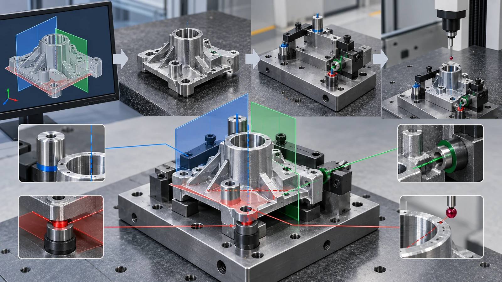
A manufacturing engineer cannot see intended use inside a CAD model. The model shows shape; the drawing and specifications show controlled requirements; the risk file explains why some features matter more than others. DFM connects these layers without allowing manufacturing convenience to erase a safety or performance requirement.
The design team should identify critical functions, interfaces, loads, surfaces, and failure modes before asking a supplier to optimize cost. The parent medical device design guidelines page covers broader design principles. DFM narrows the focus to whether approved processes can create, measure, assemble, and maintain the design.
Good DFM removes unnecessary manufacturing difficulty while preserving every requirement that gives the device its intended function.
Design the Interfaces First
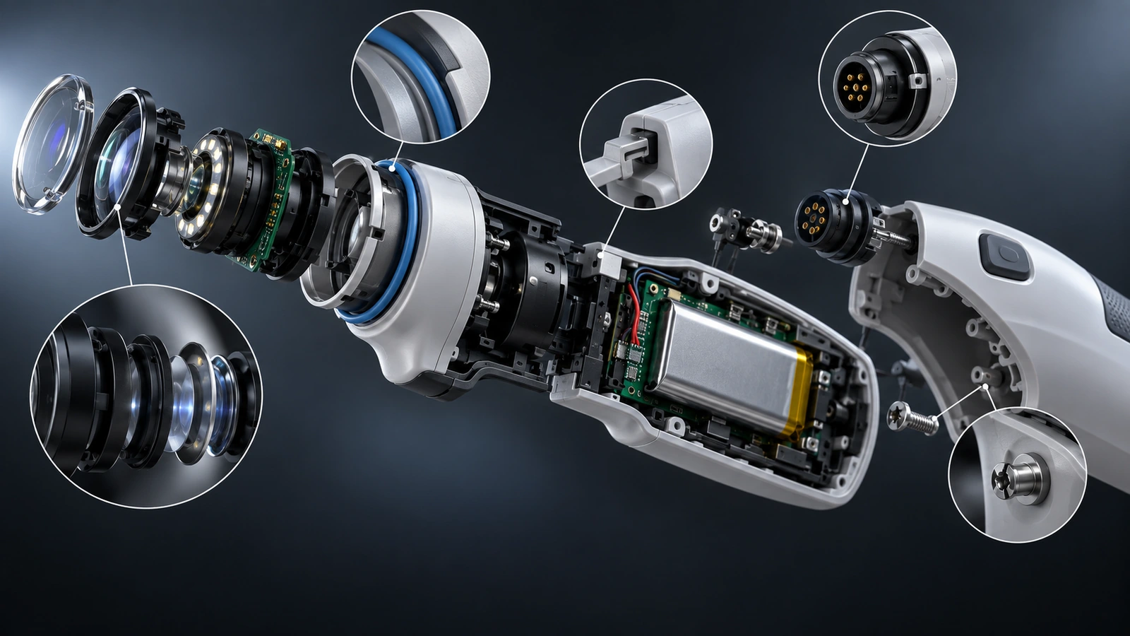
Most production problems emerge where parts meet: a seal against a groove, a sensor against a datum, a molded cover against a sheet-metal chassis, a cable through a strain relief, a bearing inside a machined pocket, or a user-contact surface around a fastener. Interface-first design exposes the features that deserve coordinated tolerances and inspection.
Create an interface control sheet
- Name the mating components and their revisions.
- Describe the function: locate, seal, slide, clamp, conduct, insulate, or transfer load.
- Identify the functional datums and load direction.
- Define material and surface interactions.
- Calculate the realistic tolerance stack.
- State the assembly and inspection method.
- Link each critical interface to a requirement or risk control.
This sheet prevents component teams from independently optimizing features that must work together. It also helps a contract manufacturer understand why a seemingly small geometry change requires customer approval.
Spend Tolerance Where Function Needs It
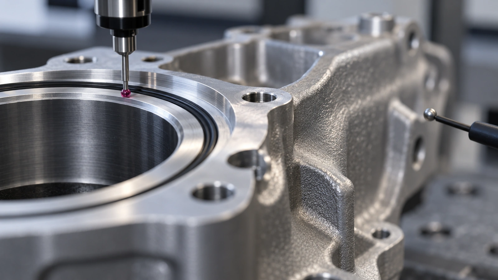
Tight tolerances increase machining time, tool wear, inspection complexity, molding risk, scrap, and supplier disagreement. Loose tolerances at the wrong interface create assembly, sealing, optical, or motion failures. The objective is not to make every number generous; it is to allocate variation deliberately.
| DFM question | What it prevents |
|---|---|
| Which tolerance directly controls function? | Tightening unrelated dimensions |
| Are datums accessible in manufacturing and inspection? | Different interpretations of the same drawing |
| Does the stack include assembly and process variation? | Parts passing individually but failing together |
| Can the method resolve the acceptance limit? | False confidence from weak measurement |
Use the medical device tolerances framework to connect functional need, process capability, and measurement method. A supplier request for tolerance relief should include the affected process, predicted benefit, and evidence that function remains protected.
Choose a Process Route by Evidence Stage
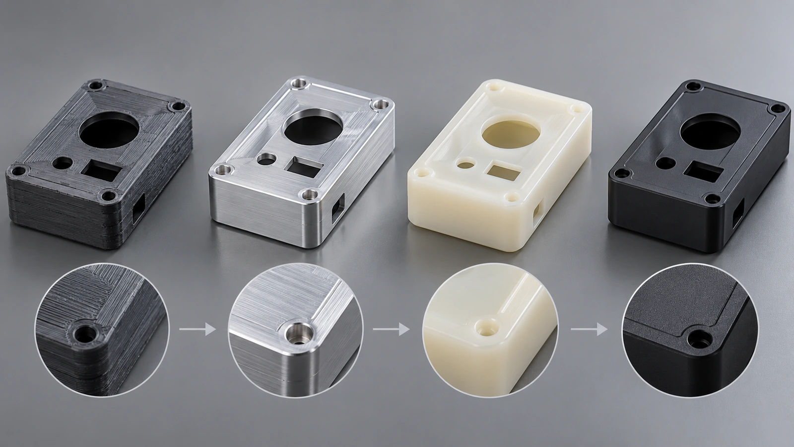
The best process for ten prototypes may not be the best process for ten thousand production units. DFM should preserve what the current build needs to learn while keeping future transition risk visible.
| Build stage | Primary evidence | DFM priority |
|---|---|---|
| Concept | Envelope, ergonomics, architecture | Fast change and clear interfaces |
| Functional prototype | Fit, load, motion, thermal, fluid behavior | Representative material where needed |
| Verification | Requirements and risk-control evidence | Controlled configuration and justified equivalence |
| Pilot | Tooling, fixtures, work instructions, yield | Production-intent route and records |
| Production | Repeatability, capacity, traceability, change control | Stable process window and supply continuity |
CNC machining, sheet metal, 3D printing, vacuum casting, molding, die casting, and rapid tooling can each be correct at different stages. The choice should be recorded with the limitations of the resulting evidence.
Make Correct Assembly the Easy Assembly
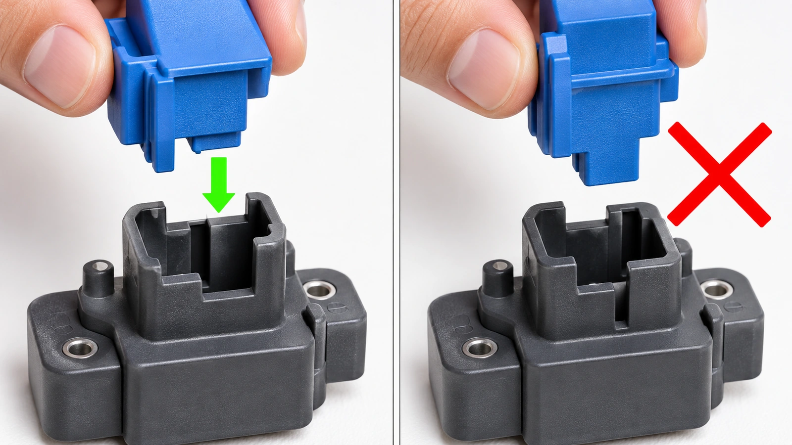
Assembly design should prevent or reveal errors. Symmetric parts that can be installed backward, identical connectors with different functions, hidden fasteners, uncontrolled adhesive volume, and inaccessible inspection points create dependence on operator memory.
Error-proofing opportunities
- Use keyed or asymmetric locating features where orientation matters.
- Separate connectors physically or visually when misconnection is hazardous.
- Provide lead-ins and hard stops rather than relying on alignment by feel.
- Design torque and tool access before enclosure surfaces are fixed.
- Control adhesive bond line and overflow paths through geometry.
- Expose test points and inspection views without requiring disassembly.
- Define serviceable versus permanent joints intentionally.
Assembly fixtures should reference the same functional datums used in the drawing. If a fixture bends the component into alignment, the released assembly may contain residual stress or hide component variation.
Design Features That Can Be Inspected
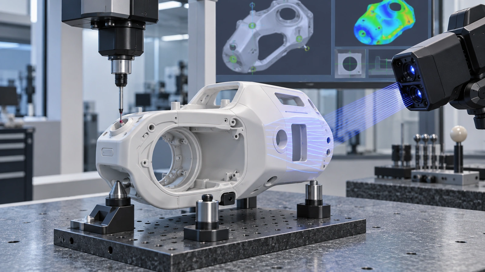
A requirement that cannot be measured reliably will create disputes or false confidence. Ensure probes, optics, gauges, leak-test connections, and reference surfaces can reach the feature without damaging or distorting it. Provide enough straight length for threads, bores, seals, and surface measurements.
Inspection should represent function. If a molded housing flexes during measurement but is constrained in the device, define the fixture state. If an optical element is aligned to assembled datums, measuring isolated component dimensions may not be sufficient. The design, assembly, and measurement states should be explicit.
The resulting plan connects naturally to medical device quality control: risk determines the characteristic, the characteristic determines the method, and the method produces a release decision.
Run a Risk-Based DFM Review

A useful DFM review is a cross-functional conversation, not a supplier redline sent after design release. Include design, manufacturing, quality, assembly, sourcing, and relevant regulatory or clinical perspectives. Prioritize findings by product risk, evidence impact, schedule, cost, and reversibility.
Review the design in layers
- Architecture: process choices, interfaces, access, and part count.
- Component: geometry, material, tolerance, tooling, and surface.
- Assembly: sequence, error proofing, fixtures, joining, and testing.
- Quality: CTQs, measurement, traceability, and acceptance standards.
- Lifecycle: cleaning, sterilization, service, repair, packaging, and changes.
Record each decision, rationale, owner, and affected document. Closing a DFM comment means more than changing CAD; drawings, specifications, risk files, test methods, and supplier quotations may also need revision.
DFM With Jucheng

Jucheng Precision can review parts and assemblies across CNC machining, sheet metal, 3D printing, vacuum casting, injection molding, reaction injection molding, die casting, rapid tooling, finishing, and assembly. Cross-process review helps teams compare routes instead of optimizing one process before confirming that it fits the product stage.
Provide models, drawings, quantities, material and finish requirements, critical interfaces, current build stage, and open risks. Jucheng can identify inaccessible features, tolerance conflicts, tooling issues, assembly risks, and inspection needs before quotation and production.
DFM FAQ

When should medical device DFM begin?
Begin when architecture, interfaces, materials, and processes are still changeable. Repeat the review when the design, supplier, process route, tooling, or production volume changes.
Does DFM mean relaxing every tolerance?
No. It means protecting functional tolerances and removing precision that does not add value. The review may tighten a critical relationship while relaxing unrelated dimensions.
Can a supplier change the design during DFM?
A supplier can propose changes and explain manufacturing impact. The design authority should assess effects on requirements, risk controls, verification, regulatory documentation, and other components before approval.
How is DFM different for prototypes?
Prototype DFM prioritizes the question the build must answer and supports rapid change. Production DFM adds tooling, process windows, yield, automation, inspection, capacity, traceability, and change control.
What files are needed for a DFM review?
Provide current 3D models and drawings, quantities, materials, finishes, critical features, assembly context, build purpose, and required inspection or documentation. Mark unresolved requirements so the supplier does not make hidden assumptions.
Design the Manufacturing Decision, Not Only the Part
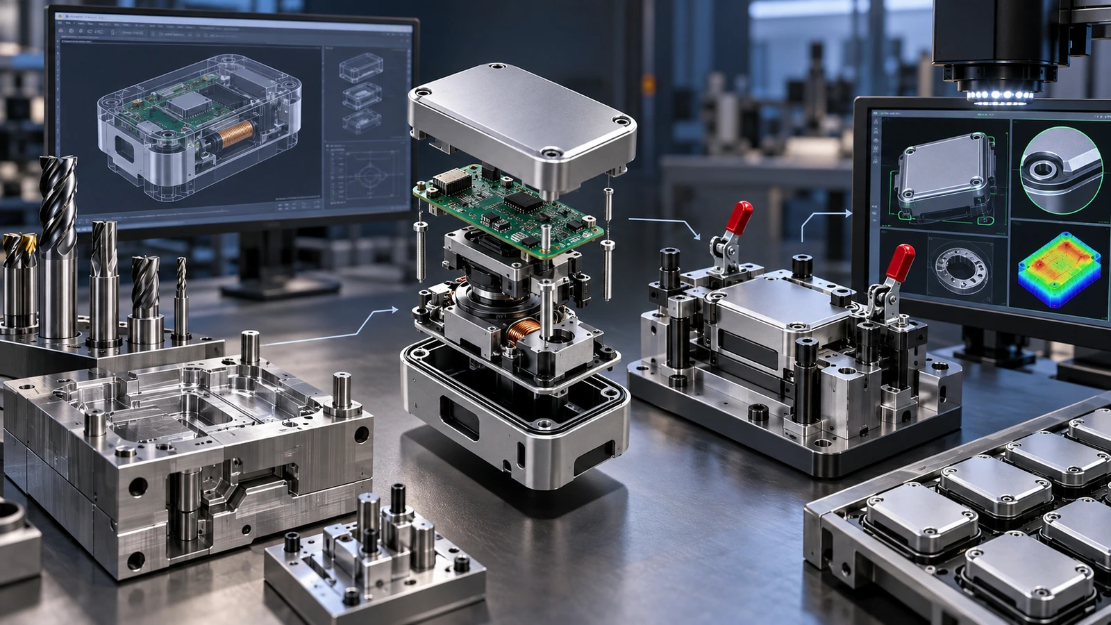
A manufacturable medical device is one whose intent can survive translation into materials, processes, tooling, assembly, inspection, records, and controlled change. If the design can only be built correctly by the person who invented it, the DFM work is unfinished.
Share your files with Jucheng for DFM and quotation review before committing to tooling or production.

