


A microfluidic manifold is a routing component, but the hardest manufacturing questions often sit at the boundaries between channels, seals, ports, and the surfaces that locate a mating plate. A passage can be open and still be in the wrong position; a flat sealing land can look clean while a cross-drilled intersection retains a burr. The design should therefore describe both the fluid path and the mechanical interfaces that make the path testable. This article addresses manufacturing planning for drawing-defined manifolds and development parts, not clinical performance or diagnostic claims. Jucheng Precision’s medical CNC machining overview is relevant when the geometry and material are suitable for machining and the project provides controlled acceptance requirements.
Contents
- Map every port and intersection before choosing a route
- Anchor the channel network to seal and mounting datums
- Decide whether to machine one block or assemble layers
- Control burrs at cross-drilled passages
- Select material against the specified fluid and process
- Treat seal lands as measured features
- Define cleaning and internal inspection boundaries
- Build an RFQ around the testable fluid path
- Frequently asked questions
Map every port and intersection before choosing a route
Start with a passage map. Identify inlets, outlets, cross-drills, plugged openings, channels, seal lands, mounting holes, and any windows or fluidic interfaces. Label which passages connect and which must remain isolated. This may be shown in a drawing view, section, or controlled model; a shaded rendering often hides the relationships that matter for machining and inspection. Clarify whether channel geometry is fully functional or whether the prototype is intended only for package review. Record channel size, position, surface requirements, and permissible edge transitions as the design authority defines them. If a channel is too small or deep for the proposed machining route, raise that limitation at DFM rather than silently changing the geometry.
Anchor the channel network to seal and mounting datums
Port locations are meaningful only relative to the interface that connects the manifold to another component. Define the mounting plane, locating features, seal boundaries, and coordinate origin. State how the channel network relates to these references. If a mating plate closes one side of an open channel, its location and seal pattern are part of the manufacturing interface and should be included in the review package. Do not use “port alignment” as a substitute for a defined tolerance. Identify the relevant position or profile characteristics and how they will be measured. If an assembly includes multiple layers, state whether each layer is inspected separately and how the assembled registration is verified. A small offset can matter to a narrow passage, so the drawing must communicate the requirement clearly.
Decide whether to machine one block or assemble layers
A one-piece manifold can reduce assembly interfaces but may contain passages that are difficult to reach with a tool. A layered construction can make channels accessible and support a flat cover, but it introduces alignment, joining, and sealing boundaries. Polymer, aluminum, and stainless-steel designs can also require different process and finishing choices. The best concept depends on channel geometry, fluid compatibility, pressure conditions, quantity, cleaning requirements, and intended validation.
| Construction | Potential benefit | Manufacturing issue to resolve |
|---|---|---|
| Machined block with cross-drills | Consolidated body with defined external interfaces | Tool reach, intersections, plugs, burr removal, and inspection access |
| Layered plates | Open channels may be accessible before assembly | Registration, joining method, seal boundary, and trapped contamination |
| Polymer body | Can suit a design whose material and geometry are defined for polymer processing | Resin compatibility, feature limits, dimensional behavior, and process route |
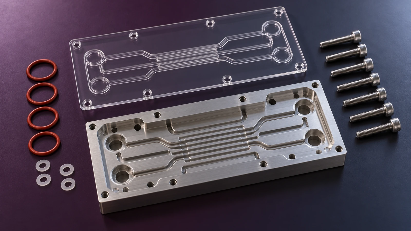
Jucheng’s medical manufacturing-process guide gives a broad route-selection context. It does not replace a material compatibility review or the project’s verification plan.
Control burrs at cross-drilled passages
Intersecting holes can leave a burr at the junction even when both drilled openings meet their nominal dimensions. The design should identify where edge breaks are permitted and where a sharp transition or defined corner must remain. Specify the cleaning and inspection approach for internal intersections. A general deburr note may not be enough when a burr could obstruct a narrow path or contaminate a test.
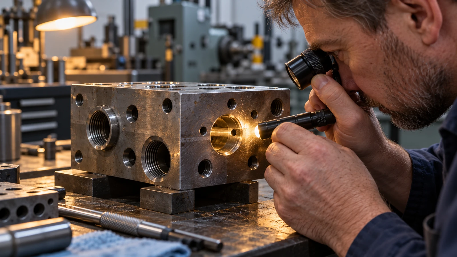
Consider whether the passage can be reached for deburring and whether inspection can verify the result. Process choices might include a toolpath that reaches the intersection, a defined assembly sequence, or an agreed inspection method. Do not promise a perfectly burr-free hidden network based only on an exterior visual check. The acceptance method should state what evidence is practical and relevant.
Select material against the specified fluid and process
Material selection depends on the intended fluid, exposure, temperature, pressure, dimensional needs, and downstream cleaning or sterilization requirements where applicable. This article does not recommend a material for any particular diagnostic or clinical use. The customer must define an approved grade and any compatibility requirements. A material label such as “plastic” or “stainless” is too broad for a controlled manufacturing order. Machining characteristics also matter. Aluminum, stainless steel, and engineering plastics such as PEEK or polycarbonate behave differently under cutting, clamping, and finishing. Confirm the exact grade and condition, and state whether a substitute is permitted. Jucheng’s medical materials overview can help organize the discussion; the approved specification governs the actual selection.
Treat seal lands as measured features
Sealing depends on the mating design, seal type, compression, surface condition, and assembly. Define the land width, flatness or profile requirement, finish, and relationship to ports according to the drawing. Identify whether any coating or treatment is present and when dimensions are evaluated. If a gasket or O-ring is supplied, include its controlled interface information so the supplier can understand the stack. If the component is subject to a leak or pressure test, specify the configuration, plugged ports, fluid or gas, test conditions, duration, and acceptance rule. A successful test reports only that defined configuration and condition. It does not prove material compatibility, long-term reliability, cleanliness, or clinical suitability unless those questions have separately defined evidence.
Define cleaning and internal inspection boundaries
Internal passages can trap chips, coolant, or finishing residue. State required cleaning, drying, packaging, and cleanliness evidence in the purchase documents. Do not assume a supplier can infer a particle limit or cleanliness level from “medical manifold.” When a validated cleaning process is required, the responsible organization should define the process and acceptance criteria. Inspection can combine dimensional checks, visual examination through accessible ports, flow or leak checks, and documented process controls where specified. Each method answers a different question. Define whether the report must include channel dimensions, port positions, test results, material records, or all of these. Make sure the measurement state and part revision are recorded to avoid comparing unlike builds.
Build an RFQ around the testable fluid path
Include a revision-controlled 3D model, drawing with sections, passage map, material and condition, quantity, finish, cleaning requirements, seal and mating-part definitions, and the inspection or functional test plan. Mark connected and isolated passages, hidden intersections, critical seal lands, and datum references. State the intended development stage and whether the part is expected to support a specific bench test. Ask the supplier to flag tool-access limits, burr risks, areas that cannot be directly inspected, and assumptions in any leak-test fixture. A focused discussion makes the fluid path, mechanical interface, and acceptance evidence visible together. It also keeps manufacturing scope separate from unprovided clinical or regulatory claims.
Frequently asked questions
Does a leak test verify every manifold requirement?
No. It checks a defined assembly under stated conditions. It does not automatically verify channel dimensions, burr condition, cleanliness, material identity, or other drawing characteristics.
Is a layered manifold always easier to manufacture?
No. It may improve channel access but creates alignment, joining, and sealing interfaces. Compare it with a one-piece design against the actual geometry and test plan.
Who defines fluid compatibility and cleanliness acceptance?
The customer or responsible design authority should provide the approved material, exposure, cleaning, and acceptance requirements in controlled documentation.