


An orthopedic reamer coupling transfers rotation from a driver or handpiece to a reamer assembly. Its interface may use a square or keyed drive, a cross-pin, a spline, a latch, or another design-specific feature. Small differences in engagement, axial retention, and concentricity can change how the components seat during assembly. A useful orthopedic reamer coupling drawing therefore describes the connection as a complete interface, not merely a hole or a drive slot.
This article addresses prototype geometry, machining communication, and inspection planning. It does not make claims about clinical safety, surgical performance, sterilization validation, regulatory clearance, or suitability for patient use. Those issues require device-specific evidence and the responsible manufacturer’s quality and regulatory processes.
Map the torque path through the interface
Start with a section view or assembly model that shows how torque enters the coupling, passes through the engagement feature, and reaches the reamer. Identify the drive feature, centering surfaces, axial stop, retention mechanism, and any clearance needed for attachment or release. Not all couplings use the same geometry, so do not assume that a square drive, pin, or latch is universal.
For an orthopedic reamer coupling, the drawing should make clear whether torque is carried by one surface pair or distributed across several faces. If a cross-pin carries load, show its axis and relation to the surrounding slot or bore. If a keyed feature provides angular orientation, define its position relative to the coupling’s centering axis. If a shoulder sets insertion depth, control that shoulder from the same reference that locates the drive feature.
These relationships help the design team ask meaningful questions: Can the assembly reach the intended seated position? Is the coupling centered before torque is applied? Does the retention feature prevent unintended axial separation under the design’s stated conditions? The drawing owner must supply the required limits and validation method. A machining supplier can manufacture and measure stated features but cannot infer a clinical risk threshold from a part name.
Separate drive fit, centering, and axial retention
Three functions are often discussed together but should be reviewed separately. Drive fit concerns the geometry that transmits torque. Centering concerns how the reamer and driver share an axis or locate radially. Axial retention concerns whether the components remain engaged along their length. A single clearance value cannot describe all three behaviors.
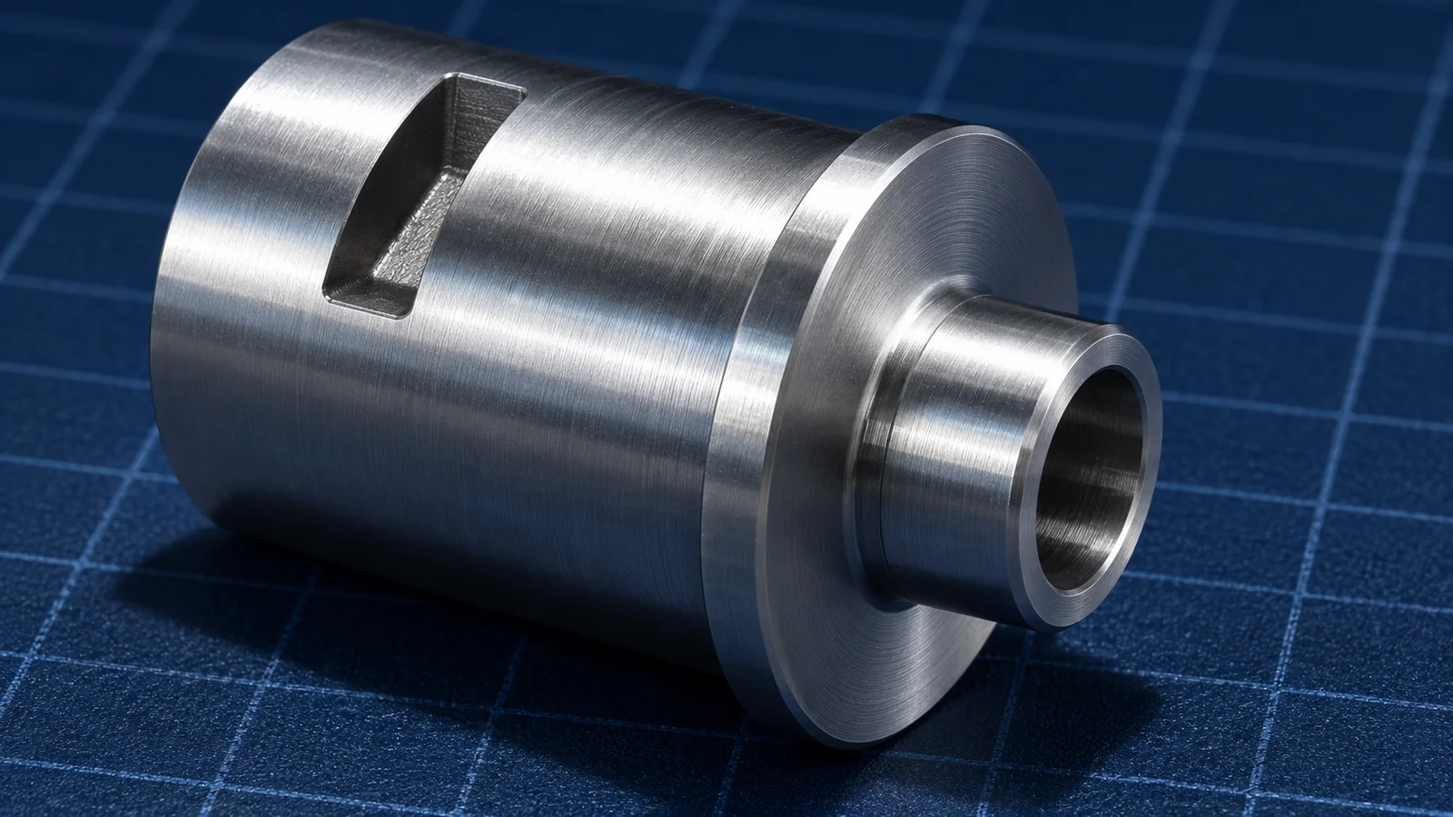
For example, a square or polygonal drive can have the correct across-flats dimension while its position is offset from the centering bore. A pin can fit its cross-hole while the axial stop is too far from the drive interface. A latch can engage yet leave excessive axial play if the seating surfaces are not defined. The drawing should state the relevant sizes and geometric relationships and define how fit is evaluated.
Consider a hypothetical prototype inspection in which the coupling slides onto the driver but appears to wobble. First isolate the centering diameter and axis, then check drive-feature position, axial seat, and retention play. Compare the result with the drawing and approved mating component. Do not automatically reduce every clearance; a change might make attachment difficult or alter the intended release behavior. This is an illustrative engineering scenario, not a real clinical case or customer project.
Design around the actual mating component
A coupling cannot be fully reviewed in isolation. The driver or handpiece geometry, reamer shank, retention mechanism, and assembly sequence determine the useful datums. Provide controlled mating dimensions or an approved reference component where practical. If an interface is proprietary or supplied by another manufacturer, clarify the revision and which dimensions are controlled by each party.
Use the assembly sequence to identify inspection needs. If the reamer is inserted and then locked, the drawing may need to distinguish the insertion path from the final engaged state. If the interface can attach in several angular positions, show whether indexing matters. If it is orientation-specific, make the keying geometry unmistakable. An exploded view can help explain component order, but it does not replace toleranced details.
FDA product-classification records identify orthopedic reamers within device classifications and describe some powered instruments with reamer attachments. That public information gives regulatory context only. It does not certify a particular coupling design or prescribe its geometry. The medical-device manufacturer remains responsible for defining the intended use, risk controls, validation, and documentation applicable to its product.
Plan machining for small features and clean interfaces
Couplings may combine a turned pilot, a milled drive slot, a cross-hole, a latch groove, internal geometry, or a surface that acts as an axial stop. The process plan should preserve the centering axis while creating the torque-transfer and retention features. The order of operations depends on part size, material, feature access, specified tolerances, and whether secondary finishing is required. There is no universal process sequence for every coupling.
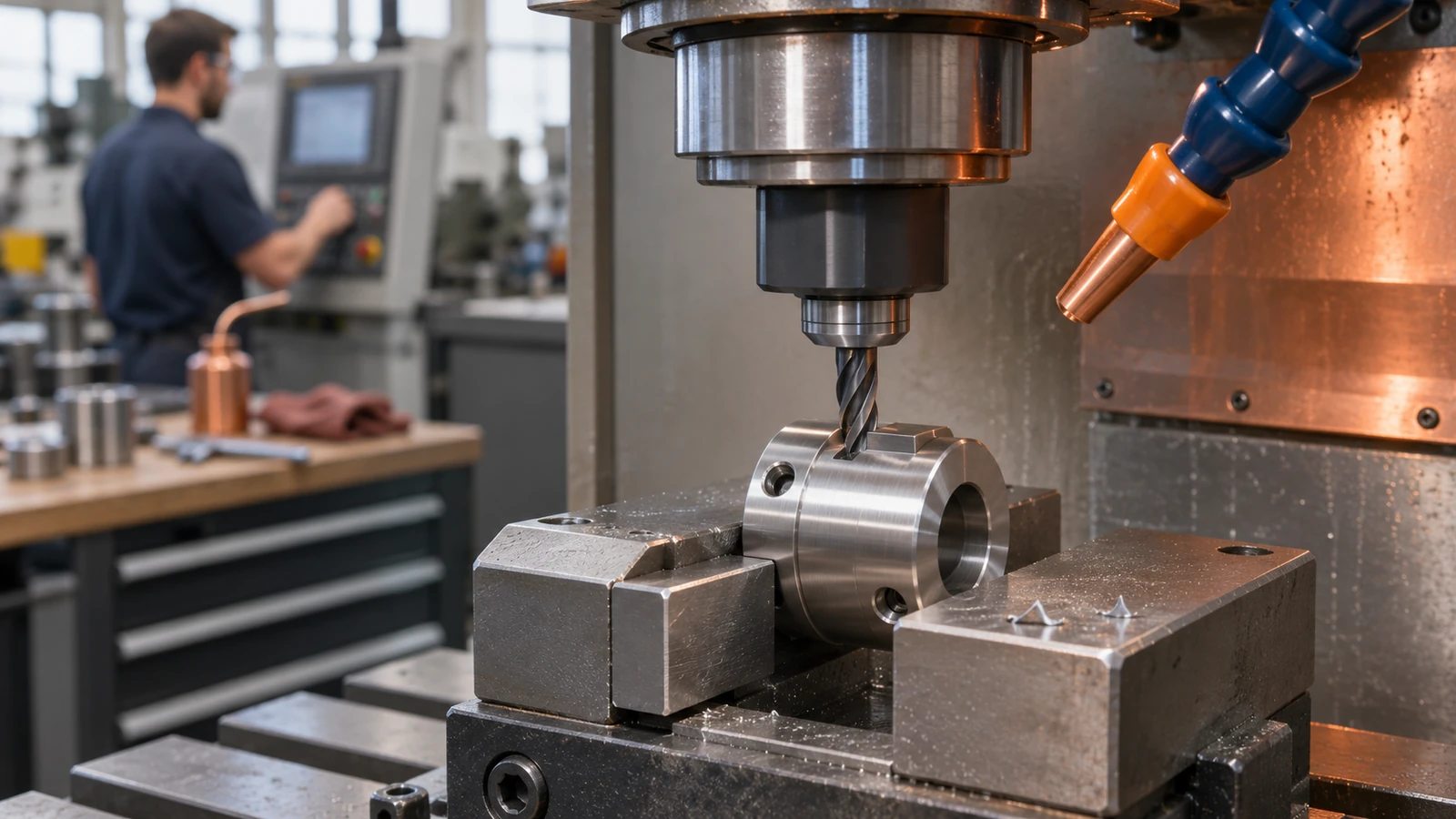
Review cutter access to internal corners, tool reach into a slot, burr formation at cross-holes, and how the part will be supported during machining. A sharp burr in an assembly path can obstruct seating; uncontrolled deburring can also alter a functional edge or reduce a contact surface. The drawing should identify edges that need a specified treatment and distinguish them from edges where a general note is acceptable.
If the part uses stainless steel or another alloy, specify the exact grade and condition rather than relying on the generic term “medical grade.” Material selection, corrosion behavior, and compatibility with cleaning or sterilization are device-specific questions. A material machining overview can support process discussion but cannot establish biocompatibility or device suitability.
For the site’s relevant machining scope, see CNC milling and turning capabilities. When the approved design specifies stainless steel, the stainless steel machining overview provides material-navigation context. Neither page implies that a particular alloy is appropriate for a surgical instrument or that a finished device has been validated.
Build an inspection plan that tests each function
List the coupling characteristics by function: drive-feature size and position, centering diameter and axis, axial stop location, retention-feature dimensions, and any specified surface requirement. Then select methods that can evaluate those characteristics against the stated datums. A plug gauge may assess a bore size; it does not necessarily establish concentricity. A test fit can reveal assembly interference, but it does not replace dimensional inspection or a defined functional test.
Where a functional fixture is used, identify the mating driver, fixture revision, insertion orientation, engagement criterion, and what the test does not establish. If the project requires torque testing, state the assembly condition, loading direction, procedure, instrumentation, and acceptance criteria supplied by the responsible design team. Do not invent a torque threshold or translate a qualitative “fits” observation into evidence of clinical performance.
Record part identity, drawing revision, material documentation, and measurement setup. If the design changes, retain a clear comparison of old and new features. For regulated-device development, manufacturing inspection is one part of a broader quality system; it does not by itself demonstrate compliance with every applicable regulation or standard.
Prototype review checklist
- Is the torque path shown from driver to reamer?
- Are centering features distinct from torque-transfer surfaces?
- Is the axial stop and retention method clearly defined?
- Are angular indexing and insertion orientation specified if needed?
- Does the drawing show the relevant mating part or controlled interface dimensions?
- Are material grade, condition, finish, and secondary processes explicit?
- Does the inspection plan separate dimensional checks from functional or validation tests?
Frequently asked questions
What should be checked first on a reamer coupling?
Start with the specified torque-transfer feature, centering interface, and axial seating or retention relationship. The design drawing determines which one is critical and how it is measured.
Does a tight drive fit guarantee low wobble?
No. Wobble can relate to centering surfaces, axis alignment, mating-part condition, axial seating, or measurement setup. Drive clearance alone does not describe the full interface.
Can a prototype shop recommend an alloy for surgical use?
The design authority or device manufacturer must select and approve the material. The shop can review machinability against the stated specification but should not infer clinical suitability.
Does a successful fit check validate clinical performance?
No. A fit check evaluates a defined assembly condition. Clinical performance, sterilization validation, regulatory status, and other device-level requirements need separate evidence.
Sources and scope
The FDA’s product classification record for orthopedic manual reamers and the agency’s record for powered instruments and attachments provide regulatory classification context. They do not specify a particular coupling’s dimensions or prove the suitability of any prototype. Apply the device manufacturer’s approved design, risk analysis, and validation requirements.

