


A quadruped robot can pass a static inspection and still move poorly. Often the cause is not one dramatic failure but a stack of small interface errors: a bearing seat is slightly off-axis, a link twists under load, a motor housing transfers heat to a sensor, or a fastener pattern forces assembly into a strained position. These details make quadruped robot parts machining a system problem, not a matter of producing isolated shapes from CAD.
The useful question is not simply whether a leg link can be machined. It is whether the link, joint housing, actuator mount, and body interface can be produced and inspected as a compatible set. That connects drawing review, prototype iteration, datum planning, material choice, finishing, and repeatable inspection to the wider robotics and automation manufacturing program.
Start with the load path, not the silhouette
A leg link may look like a light, sculpted beam, but its job is to transmit forces between joints while resisting bending and torsion. Stance, gait, payload, stride, and shock events determine where structural demand appears. Removing material uniformly can weaken a rib or leave an unsupported wall that vibrates. A better review traces force from foot contact through the lower link, joint, upper link, and body attachment, then asks which surfaces actually carry load.
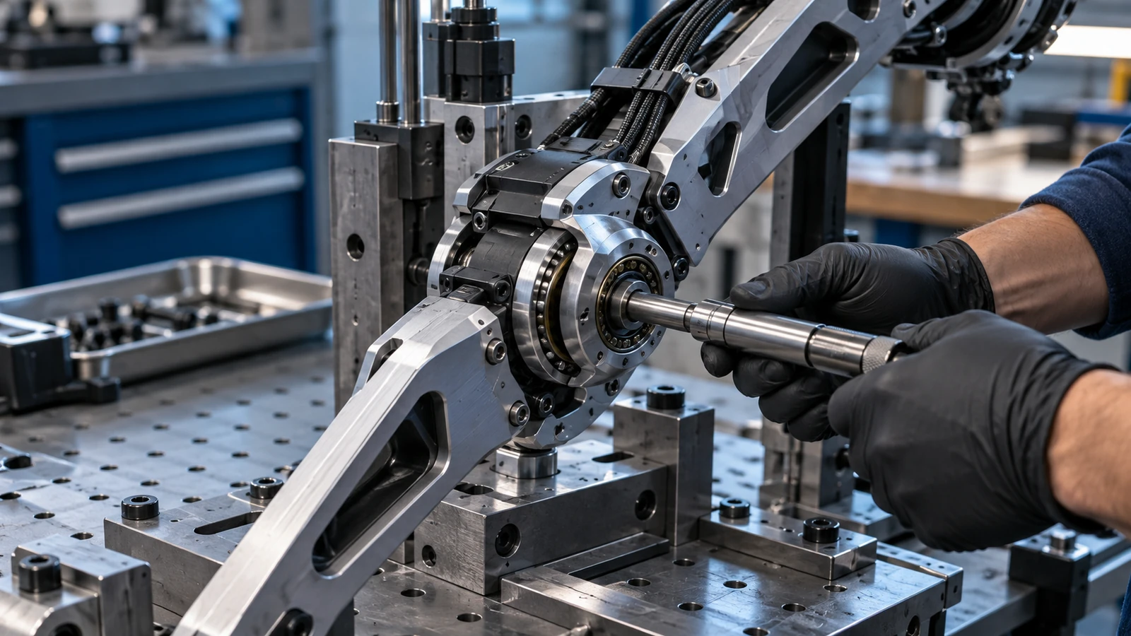
That load-path view changes manufacturing decisions. Pocket depth, rib direction, wall transitions, and fastener bosses should be judged against installed constraints, not only a rendered model. If a component is expected to change after gait testing, the first build may prioritize adjustment access and dimensional learning over cosmetic finish. A prototype manufacturing route can support evaluation before a team commits to repeat production.
Weight also has a location. Reducing mass near the distal end of a leg can affect moving inertia differently from removing the same mass near the torso. Preserve material around bearing seats, motor interfaces, and high-stress transitions while considering pockets elsewhere. The correct balance depends on simulation assumptions and physical tests; lighter is not automatically better when stiffness, fatigue, impact, and thermal behavior matter.
Treat joint interfaces as a tolerance chain
Motion depends on relationships between paired bearing bores, a motor pilot, a gear interface, a cover, and the link mounting face. If each dimension is considered alone, a drawing can appear reasonable while the assembled stack produces binding, uneven preload, or an axis that is not square to the link. Identify the functional datum scheme first. Then define which dimensions locate the joint, which provide clearance, and which can be adjusted during assembly.
Separate critical-to-function features from convenience dimensions. Bore alignment, face perpendicularity, and motor-pattern position may deserve a controlled setup and documented inspection. Edge breaks, non-mating contours, and some cosmetic surfaces may not need the same treatment. This avoids accumulating tight tolerances that add cost without improving gait or serviceability. For related component-level manufacturing considerations, see the site’s industrial robot parts machining article; each quadruped still needs its own datums and load assumptions.
Clearance is not a substitute for alignment. A loose fit may hide mismatch during bench assembly but allow impact, fretting, or repeatability problems later. A close fit can make assembly sensitive to coating thickness, burrs, temperature, or fastener sequence. State the intended fit and assembly method on the drawing or in a controlled note rather than expecting a supplier to infer it from a rendering.
Choose material around mass, stiffness, and service
Aluminum alloys are often considered for structural links because they combine relatively low density with useful machinability and stiffness. Steel may suit a compact, highly loaded shaft, pin, or wear interface where strength, contact behavior, or thread durability outweighs mass. Engineering plastics can work for covers, cable guides, insulating spacers, or low-load fixtures, but respond differently to heat, creep, moisture, and fastener preload.
| Part zone | Candidate direction | Design question |
|---|---|---|
| Long structural link | Machined aluminum | Will it resist bending without excessive moving mass? |
| Bearing or drive interface | Metal selected for load and wear | Are contact stress and finish compatible? |
| Guard or cable feature | Engineering polymer | What heat, impact, and service-life conditions apply? |
Material names alone do not establish suitability. Exact grade, temper or condition, stock form, and finish matter. A machined prototype may use a different material or process than a later molded component, so document which test results transfer and which must be repeated. The aluminum CNC machining material page is a starting point, not a substitute for confirming the grade and design requirements.
Plan machining around distortion and access
Thin arms, deep pockets, and asymmetric ribs can move as stock is removed. If a link is clamped aggressively, released, and measured only in the fixture, inspection may not describe its free state. A process plan should consider roughing and finishing, stock support, clamping, and when the part can relax before critical dimensions are completed. Feature access matters too: a deep wall may be visible in CAD but difficult to reach with a stable tool and reliable inspection probe.
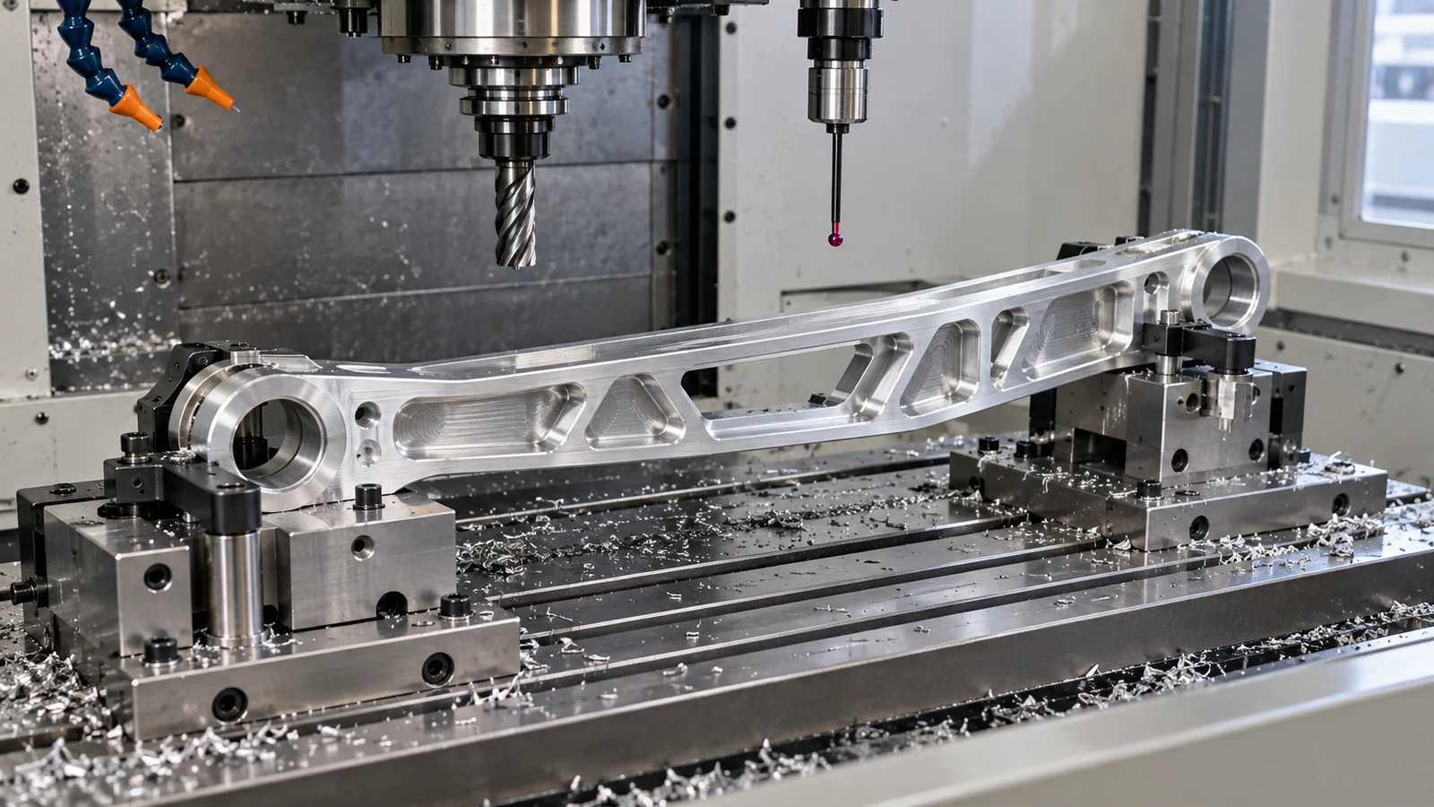
For parts with multiple mating faces, protect datum surfaces and avoid repeatedly locating from cosmetic geometry. If several setups are necessary, use reference features or fixtures that preserve coordinate relationships. Internal corners, tool radii, long-reach cutters, and chip evacuation should be reviewed early; these are design-for-manufacturing decisions, not minor shop-floor details.
Post-processing belongs in the same plan. Anodizing, coating, deburring, or another surface treatment can alter dimensions or affect electrical contact and bearing fits. Specify areas to mask, surfaces that must remain conductive, and whether appearance or wear resistance is the objective. A good bore can become a poor assembly feature if finish allowance and masking were never coordinated.
Inspect the assembled function
A coordinate report can show selected features within drawing limits, but functional checks reveal whether interfaces work together. Depending on the design, checks may include datum-based inspection of paired bores, a fixture check of joint-axis alignment, fastener access, or a trial assembly with the actual bearing and motor. Select checks from the failure modes the team wants to prevent rather than adding a generic list.
For a multi-part leg, inspection planning also needs revision control. A link from one CAD revision should not be evaluated against a joint housing from another. Identify drawing revisions, material lots, and approved deviations in the same record. If a prototype is intentionally modified by hand, document it so the next build does not inherit an undocumented fit.
A useful acceptance plan describes the measurement method as well as the nominal value. It can state the datum setup, relevant instrument or fixture, sampling approach, and part condition during measurement. If coatings or assembly loads influence results, note whether inspection occurs before or after those steps. The objective is repeatable interpretation across design, manufacturing, and receiving inspection.
Use prototypes to answer specific questions
A prototype is most valuable when its test is defined before the order. One build might check whether a revised link clears a cable route; another may evaluate joint stiffness, fastener access, or a bearing shoulder. If several questions are bundled together, a failure can be difficult to diagnose. Tie each revision to explicit hypotheses and preserve observations with the drawing revision.
The manufacturing route should match that learning goal. CNC machining can preserve metal-like behavior for structural interfaces; additive manufacturing can assess packaging or cable clearance when the part is not intended to prove final strength; molding may become relevant after a polymer housing stabilizes and volume supports tooling. A hybrid build can be useful, but document material and process differences so a successful fit check is not mistaken for fatigue or thermal validation.
What to include in a manufacturing RFQ
A useful RFQ includes a released 3D model, dimensioned drawing, material and finish callouts, expected quantity by revision, critical interface notes, inspection expectations, and the tests the part must support. Identify whether the request is for one-off prototypes, a pilot lot, or repeat batches. If the design is moving, say which features are frozen and which may change so the quote does not imply an unapproved production commitment.
Include assembly context where possible: adjacent parts, bearing or motor references, fastener sizes, cable paths, and the intended datum scheme. A model without context can hide a trapped tool path or an impossible inspection setup. Ask for DFM review of specific risks—thin walls, deep pockets, concentric bores, finishing allowances, or assembly access—instead of a generic please review.
Quadruped robot parts become dependable when structural intent, manufacturing sequence, and assembly evidence remain connected from prototype through revision. The next useful step is to provide drawings with the function of each critical interface stated, then review the proposed process against the robot’s actual gait, load, and service requirements.

