


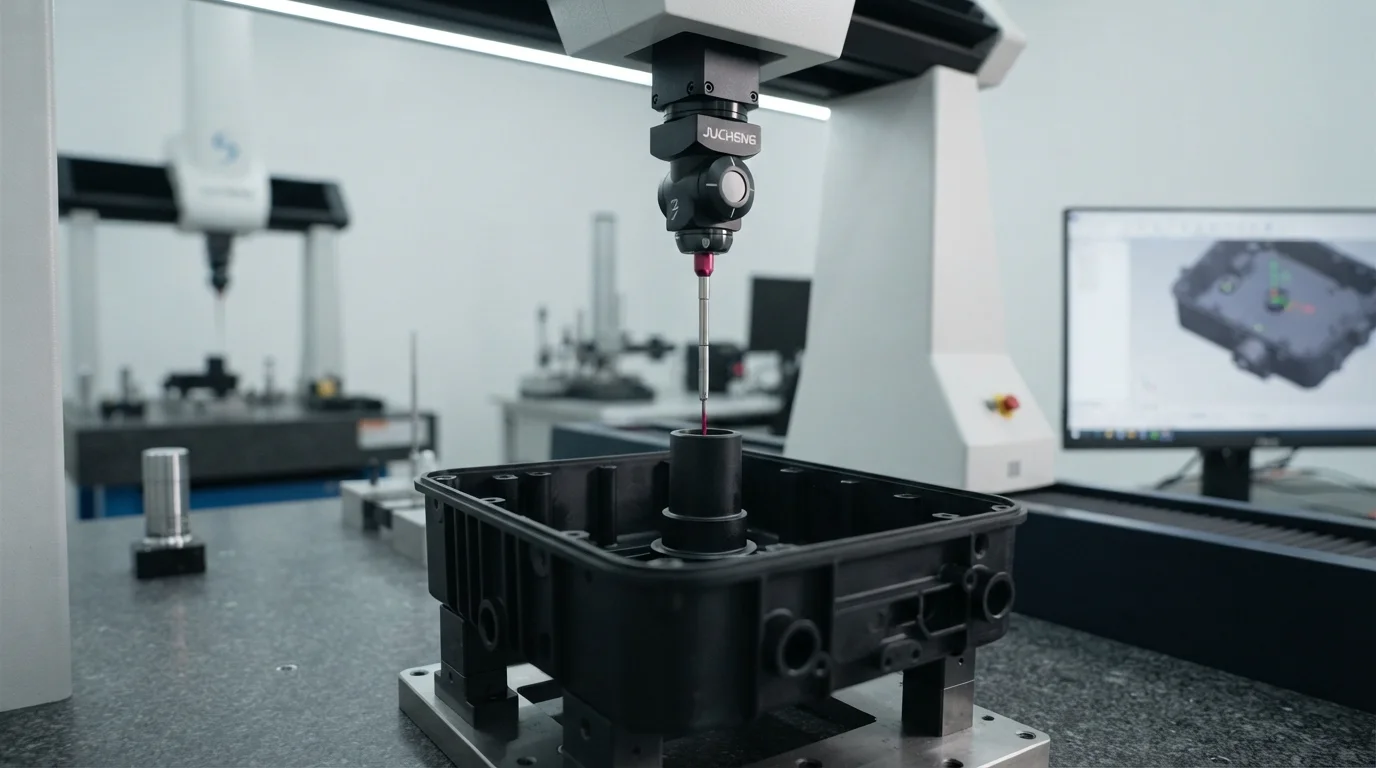
Committing massive development capital to high-volume injection molds before verifying physical part tolerances is a high-risk gamble that frequently leads to expensive tooling reworks. Sourcing high-fidelity physical models allows mechatronics groups to identify assembly interferences, validate snap-fit deflection limits, and check internal printed circuit board (PCB) clearances realistically. Product development teams use these tactile test units to perform physical drop-tests and thermal runaway simulations, ensuring components survive real-world operational environments safely. Eliminating subtle geometric errors early protects launch schedules and preserves crucial cash flow during critical product development gateways.
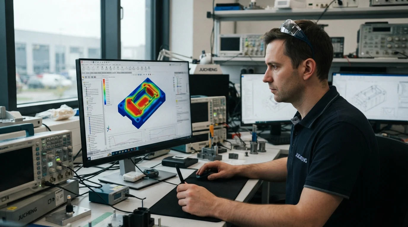
Table of Contents
1. Identifying DFM Flaws Early on the Shop Floor
2. Material Performance Testing Prior to Tooling Commits
Identifying DFM Flaws Early on the Shop Floor
Question: How are design-for-manufacturability flaws identified before tooling begins? Experienced engineers conduct detailed CAD analyses and fabricate physical prototypes to pinpoint parting line mismatches and wall thickness variations.
Jucheng Precision collaborates with engineering teams during early developmental stages by delivering comprehensive 24-hour free DFM reviews before cutting metal or pouring silicone. Factory specialists analyze CAD files manually to identify zero-draft vertical walls, deep internal undercuts, and sharp corners that complicate mold release. Using advanced software simulations helps designers predict localized polymer shearing, material knit lines, and air traps. Correcting these geometric flaws on early-stage prototypes prevents expensive hard steel tooling modifications downstream.
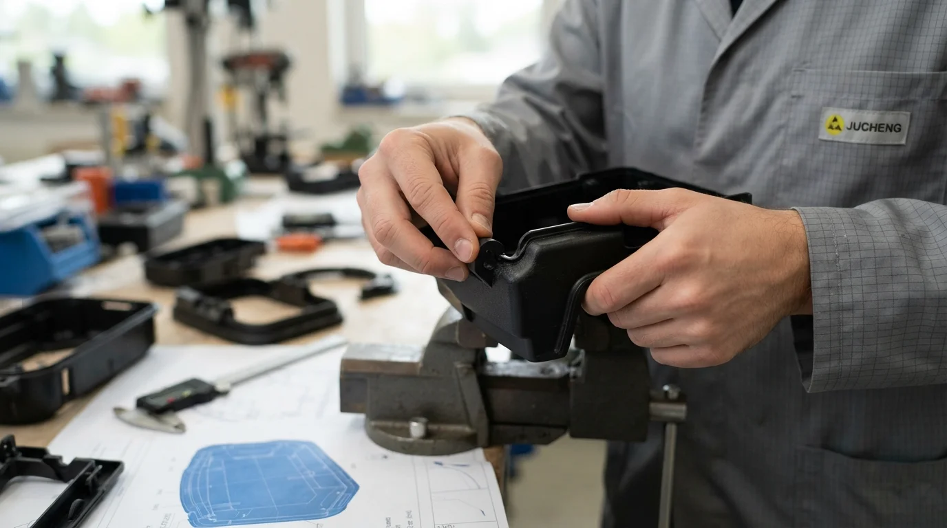
Executing physical validation tests represents the most reliable method of rapid prototyping for risk mitigation. Designers use high-resolution SLA printed parts or custom polyurethane castings to check fitment clearance before committing to volume tooling. Microscopic dimensional deviations in mating joints are easily detected when parts are physically assembled on the workbench. Early physical check-ups ensure interlocking covers snap together with a crisp, audible feedback without stressing fragile plastic ribs.
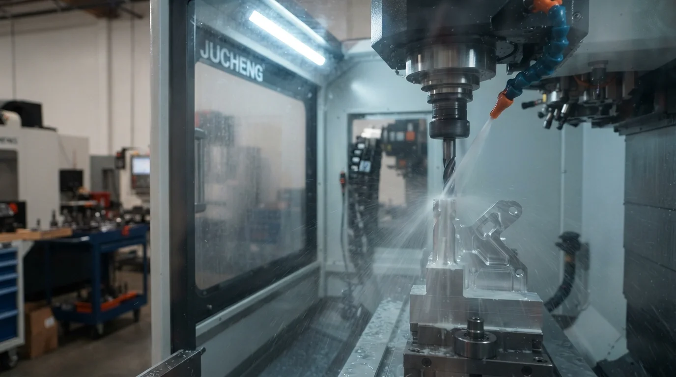
Sourcing high-fidelity functional parts milled from solid engineering blocks of ABS, Nylon (PA), or Polycarbonate (PC) provides authentic material behavior before tooling. Machined or rapid-molded engineering plastics recover their shape completely after deflection, allowing designers to perform accurate assembly checks. Symmetrical component configurations simplify holding fixtures, reducing initial setup labor hours dramatically. Standardizing non-critical clearances allows high-speed milling spindles to clear raw stock quickly, maximizing cutting efficiency.
Physical testing of structural frames under simulated dynamic load reveals whether material grain alignment affects component fatigue life. Anisotropic shrinkage and layer adhesion limitations in additive manufacturing often cause premature failures under cross-axis shear stress. Structural designers specify multi-axis milled metal billets to maintain isotropic material properties across critical load paths. Sourcing milled structural links represents a signature technique used to analyze real-world fatigue limits.
Material Performance Testing Prior to Tooling Commits
Question: Why is material validation critical before launching production? Prototype parts made from production-grade resins ensure components maintain structural stiffness and resist chemical or thermal degradation.
Selecting appropriate manufacturing methods balances raw material properties with fast turnaround times during early-stage testing. Slicing complex three-dimensional CAD files precisely allows experienced toolmakers to analyze parting lines, draft angles, and wall thicknesses using advanced mold flow simulation software. Implementing physical rapid prototyping for risk mitigation ensures your chosen polymer grade resists continuous environmental stress. This comparative table highlights baseline structural and thermal limits of common engineering materials used during functional testing:
| Material Base | Tensile Strength | Heat Deflection Temp | Primary Mechanical Advantage |
|---|---|---|---|
| Nylon 6 (PA6-GF30) | 110 MPa | 185°C | High stiffness, outstanding dynamic impact absorption |
| ABS (High Impact) | 43 MPa | 98°C | Balanced dimensional stability, ease of cosmetic finishing |
| Polycarbonate (PC) | 65 MPa | 135°C | Optically transparent, excellent drop-test durability |
Market Validation Prior to Mass Production
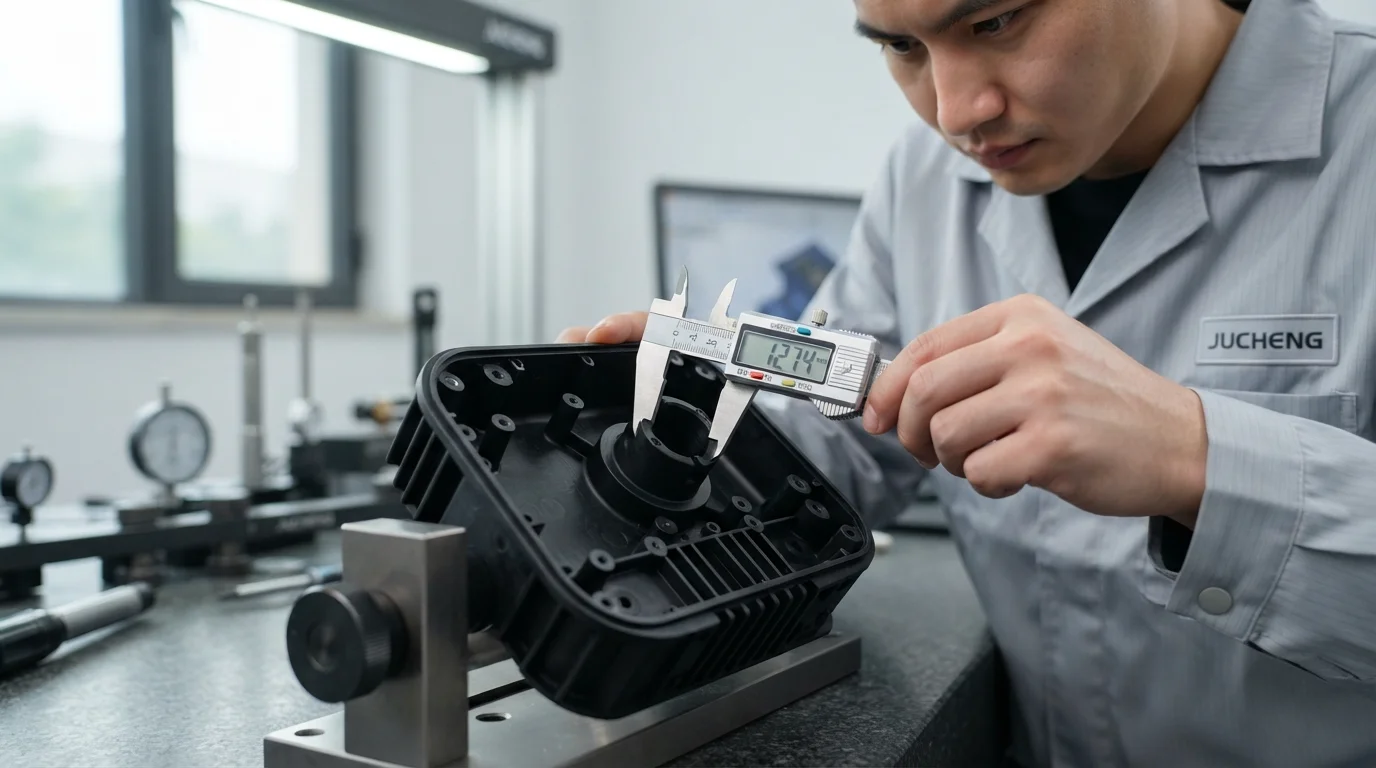
Question: How does low-volume production validate market acceptance safely? Sourcing ten to fifty units through vacuum casting or rapid tooling allows startups to gather user feedback before investing in high-volume steel molds.
Investing in high-volume, hardened steel molds requires severe upfront capital that startup budgets can rarely support without locking up crucial cash flow. Sourcing a dedicated Rapid Tooling Service using aluminum or soft steel cores delivers genuine injection-molded components from production-grade resins within weeks. Sourcing rapid tooling allows product developers to validate gating, parting lines, and draft angles under real machine pressures. Splicing raw CAD files precisely allows experienced toolmakers to analyze parting line shut-offs manually.
Understanding the baseline advantages of rapid prototyping allows mechatronics groups to bypass these high capital barriers safely during early development. Sourcing physical validation models early in your developmental cycle ensures you avoid hidden fees like mold redesigns and gating errors. Sourcing high-quality prototypes ensures your designs are built to withstand severe dynamic forces safely. Sourcing your components from our certified, single-roof manufacturing facility prevents communication errors, ensuring design changes are propagated across all stages safely.
Frequently Asked Questions (FAQ)
How does prototyping reduce overall B2B manufacturing risks?
Designing parts with gentle draft angles and generous fillets helps preserve the cavity walls, extending mold life up to forty runs. Sourcing early DFM reviews simplifies split line layouts, eliminating the need for expensive mechanical sliders in rapid molds. Implementing physical rapid prototyping for risk mitigation remains the premier choice for aerospace, medical, and automotive engineering.
Can 3D printed parts survive functional assembly validation tests?
Low-end additive printing processes cannot simulate the physical strength of production thermoplastics, making structural part testing highly prone to failure. Sourcing functional parts milled from solid engineering polymers represents a critical milestone to validate realistic mechanical wear. Sourcing early DFM reviews ensures non-critical tolerances are loosened to prevent unnecessary machining hours.
Does complex surface polishing increase overall manufacturing bills dramatically?
Manual hand-polishing, vapor-polishing, and multi-layer painting require intensive labor hours, which can double your overall project bill. Specifying standard bead-blasted or raw machine finishes for internal structures or early visual models lowers your total finishing expenditures. Product designers coordinate with manufacturing specialists to apply decorative coatings only on visible external show faces.
How can mold tooling expenses be reduced for short-run production?
Standardizing vertical draft angles, filleted corners, and nominal wall thicknesses is the primary method to prevent mold flash. Mold parting line shut-offs are hand-fitted precisely, ensuring polymer does not escape under high clamping pressures. Sourcing early DFM reviews simplifies split line layouts, eliminating the need for expensive mechanical sliders in rapid molds.

