


A rivet can look neatly centered in a flange and still leave too little material between the hole and the sheet edge. Rivet edge distance is measured from the center of the rivet hole to the nearest free edge, not from the outside of the rivet head. It is distinct from the remaining material ligament and from the pitch between neighboring holes.
For aerospace sheet-metal parts, use the released engineering drawing and applicable design or repair data to establish the required distance. A general diameter multiplier is not an approval to design a flight-critical joint. The manufacturing task is to understand that requirement, protect it through forming and trimming, and verify the finished geometry.
Measure from the hole center, not the head
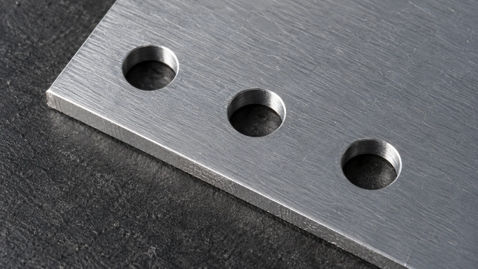
Start with the hole and the actual edge that could limit the connection. On a straight flange, the shortest in-plane distance from the hole center to that edge is the basic edge-distance measurement. A large rivet head can cover an area that appears reassuring while the hole underneath remains too close to the edge.
| Term | What it describes | Common confusion |
|---|---|---|
| Edge distance | Hole center to nearest free sheet edge | Measuring from the head perimeter |
| Edge ligament | Material between the hole perimeter and the edge | Reporting it as center-to-edge distance |
| Pitch | Center-to-center spacing along a row | Measuring the clear gap between heads |
| Row spacing | Separation between rows according to the defined layout | Using diagonal spacing in a staggered pattern without checking the drawing convention |
For a round hole beside a straight edge, the geometric ligament is edge distance minus half the hole diameter. This relationship explains why an enlarged hole reduces the remaining material even when the center position has not changed. Countersinking creates additional geometry at the surface, so the simple through-hole ligament alone does not describe the complete joint condition.
Slots, scalloped edges, relief cuts and intersecting flanges require more care. Identify the controlling free edge rather than selecting the edge that gives the largest reading. If the drawing does not make the measurement convention clear for a curved or formed surface, resolve that ambiguity before manufacture.
Why a diameter multiplier is not a design release
Common references express edge distance and aircraft rivet spacing as multiples of fastener diameter. Those rules are useful only within their stated scope. Fastener type, head style, sheet thickness, material, load path and joint configuration can change the applicable requirement. A generic internet chart cannot establish structural suitability.
The FAA’s AC 43.13-1B guidance discusses rivet layout in a defined aircraft inspection and repair context. It should not be treated as unrestricted design data for every new aerospace joint. Determine which approved or otherwise applicable instructions govern the actual work, including customer requirements.
For a component manufacturer, the key distinction is between checking conformance and approving a joint design. The supplier can flag a hole that appears close to an edge, explain the available fabrication margin and propose a review. Moving it, changing its size or substituting another rivet still needs authorization from the responsible design authority.
The existing aircraft sheet metal assembly guide provides the wider joining context. Here the focus is narrower: ensuring that the actual hole-and-edge geometry matches the ordered definition, including the effects of downstream operations.
A tolerance stack at the sheet edge
A nominal distance on the flat pattern is not necessarily the smallest distance that production will deliver. Hole location, final trim position and any forming-induced movement can consume the margin. Review the drawing’s datum system before stacking tolerances; adding unrelated plus-or-minus values can be as misleading as ignoring them.
Illustrative one-dimensional check
Suppose a hypothetical flat coupon has a nominal center-to-edge distance of 10.0 mm. In a simplified worst-case model, the hole can move 0.2 mm toward the edge and trimming can move the edge 0.3 mm toward the hole. The minimum geometric distance in that model is:
10.0 – 0.2 – 0.3 = 9.5 mm. If the actual round hole diameter is 4.0 mm, the corresponding geometric ligament is 9.5 – 2.0 = 7.5 mm. These invented dimensions demonstrate arithmetic only; neither result is an aerospace design minimum or a statement that the joint is acceptable.
This calculation assumes independent opposing extremes in one direction and no additional geometric effects. A positional tolerance zone, profile requirement or curved edge needs interpretation in the actual coordinate system. Statistical stacking should not replace worst-case analysis without a justified method and approval appropriate to the application.
Write down the source of each contribution. Is the edge defined by a profile tolerance, an overall dimension or a secondary trim operation? Is hole position measured from the same datum used to control the edge? Does coating affect the relevant acceptance condition? A traceable stack lets the team discuss the real margin instead of arguing over a single nominal value.
Where the available margin is too small, possible proposals include changing the blank geometry, revising the locating strategy or controlling final trim more closely. Each proposal has a different cost and engineering impact. The part drawing should be changed only through the applicable approval process.
Plan the holes around forming and assembly
Hole-making before forming can simplify flat-sheet access and repeatability. It can also place a hole in a region that stretches or changes shape during bending. Making a critical hole after forming may improve its relationship to the final geometry, but requires tool access, a suitable fixture and a defined datum setup.
There is no universal rule that all holes belong before or after the bend. Separate holes by function. A clearance hole far from a deformation zone may tolerate a different sequence from a close-fit assembly hole whose location controls the finished joint. Put the intended inspection stage on the manufacturing plan.
Final trimming deserves equal attention. A perfectly positioned hole can lose edge distance when a flange is trimmed later to suit assembly. Conversely, leaving excess stock does not solve the issue if it interferes with the mating part or fastener installation. The final contour, not the temporary blank edge, must meet the requirement.
Joint fit-up introduces another interface. Two sheets can each meet their separate drawings yet have insufficient hole alignment in assembly. Forcing a fastener through or casually enlarging holes changes the geometry under review. Escalate misalignment and follow the authorized disposition rather than converting an assembly problem into an undocumented hole modification.
When quoting sheet metal fabrication, provide Jucheng Precision with the formed-part definition, material and condition, relevant mating geometry and inspection stage. Include the flat pattern if available, but state which definition controls if it differs from the finished-part drawing.
Inspect the joint before access disappears
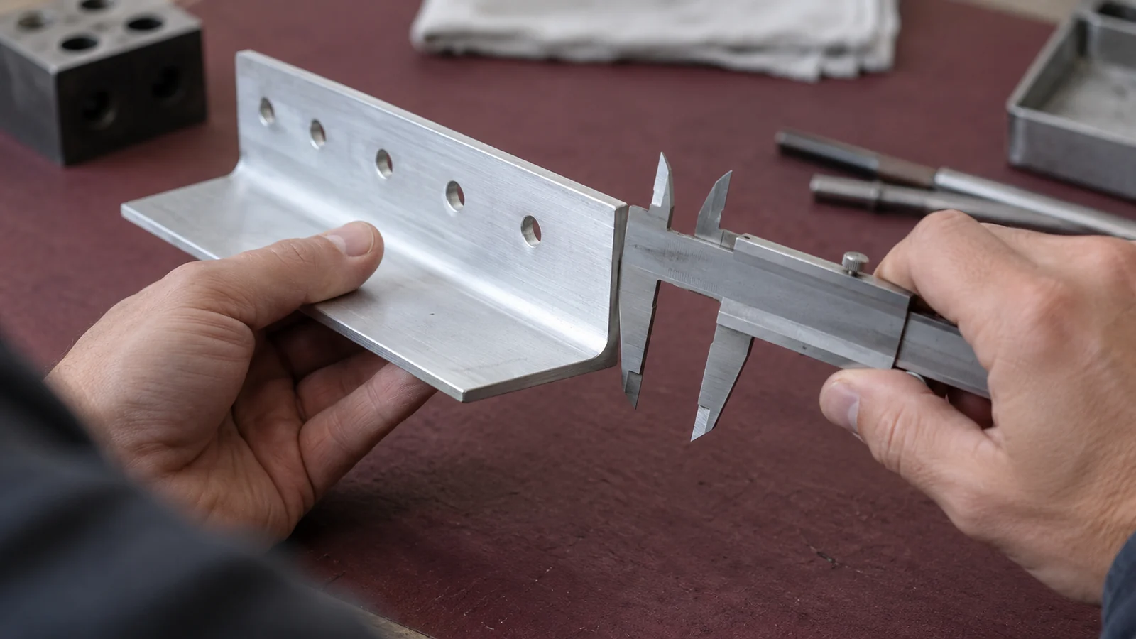
Checking an empty hole is usually more direct than inferring its center after a head covers it. Plan accessible inspection points before riveting or before the assembly blocks the edge. Choose a measurement method capable of locating both the hole and the controlling edge in the required reference frame.
Inspect more than the distance value. Burrs, edge damage, hole distortion and countersink condition can affect the joint even if a center-to-edge measurement passes. Keep dimensional conformance and surface-condition checks distinct so one favorable result does not hide another unacceptable feature.
- Confirm the correct drawing revision and final trimmed condition.
- Identify the nearest controlling edge and the relevant hole or pattern.
- Record the measurement method, datum setup and actual result where required.
- Check any separately specified hole, countersink and edge conditions.
- Hold nonconforming geometry for authorized disposition before assembly hides it.
Does deburring change edge distance?
Removing a normal burr should not be treated as permission to reshape the edge. Excessive material removal can move the controlling contour or damage the local geometry. Inspect the finished condition required by the drawing, particularly where the available margin is small.
Can a larger rivet solve a hole near the edge?
Not automatically. A larger hole removes more material and may change the required layout, installation conditions and joint behavior. Any repair or design change must follow the applicable approved data and responsible engineering decision.
The practical objective is simple: know which geometry controls, protect it through the fabrication sequence and verify it while the evidence is still accessible.

