


A satellite battery tray does more than keep cells in place. It connects a mass-bearing energy subsystem to the spacecraft structure while preserving electrical clearances, thermal paths, access for integration, and restraint through launch. A tray that is easy to machine but difficult to inspect or assemble can create late changes around connectors, harnesses, and service access.
Begin with the battery supplier’s controlled interface and the spacecraft-level safety and environmental requirements. The tray should not define cell compression, venting, electrical isolation, or thermal limits by guesswork. Its role is to provide a stable, inspectable mechanical interface for requirements owned by the battery and systems teams.
Contents
- Separate tray functions from battery requirements
- Map the interfaces before choosing a shape
- Design retention around the load path
- Keep thermal and electrical constraints visible
- Select a process from geometry and quantity
- Make the tray verifiable after finishing
- A practical release checklist
Separate tray functions from battery requirements
Write down the mechanical functions first: support the battery assembly, transfer loads into the spacecraft, preserve required clearances, and provide defined mounting or retention features. Then list the requirements that belong to other authorities, such as cell operating limits, electrical isolation, vent paths, thermal interfaces, and battery qualification. The tray drawing should reference those controlled inputs rather than silently reinterpret them.
This separation prevents a common mismatch: a mechanical part is released with adequate envelope dimensions but no clear instruction about insulation, contact area, or access. If the battery assembly requires a particular pad, barrier, insert, or surface condition, identify it in the interface control package. If those requirements are not yet available, hold the relevant design decision rather than substituting a generic note.
Map the interfaces before choosing a shape
List the mating features on both sides of the tray: battery case, spacecraft deck, harness connectors, thermal straps or pads, nearby electronics, and any access panel. Record which surfaces locate the tray and which fasteners provide clamp load. A drawing that only dimensionally defines the outer envelope leaves the assembly datum and repeatability implicit.
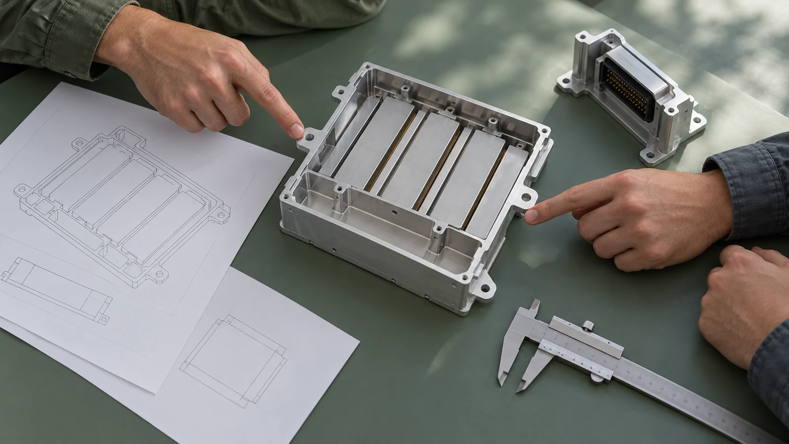
Check installation order. Can the tray be attached before the battery is installed? Can the battery fasteners be reached after the harness is routed? Is a connector blocked by a wall or lip? These questions often determine whether the design needs open sides, removable panels, access holes, or a two-piece construction.
For early programs, a full-scale fit model can reveal clashes and tool-access problems before the battery unit is available. Jucheng’s aerospace prototyping and manufacturing capability is relevant to such hardware discussions; the released dimensions and subsystem safety requirements still come from the spacecraft program.
Design retention around the load path
Retention features must transmit the expected inertial loads without creating local damage or losing access to the battery assembly. The structural team should define the load cases, load factors, attachment strategy, and any required restraint redundancy. Manufacturing can then translate that intent into controlled thickness, fastener locations, inserts, and contact surfaces.
Be cautious with thin flanges and narrow slots around fasteners. They can concentrate stress, distort during machining, or be difficult to inspect after finishing. If a strap, clamp, or lid retains the battery, identify its contact area and how clamp force is controlled. Do not specify compression values unless they are provided by the battery design authority.
For a tray made from multiple panels, define the joining method and tolerance stack between them. A bolted assembly may ease access but add mass and interfaces; a welded or bonded structure may reduce parts but introduce process controls and distortion concerns. The choice depends on program requirements and must be evaluated by the responsible structural and materials teams.
Keep thermal and electrical constraints visible
The tray may act as a thermal path, a thermal break, or a structural support with limited thermal function. Those roles should not be conflated. If the battery needs heat rejection or temperature isolation, the thermal team should define contact area, interface material, flatness, and expected operating environment. A surface finish or coating can alter contact behavior and must be part of the review.
Electrical clearances and isolation also affect geometry. Keep-out zones around terminals, connectors, and conductive fasteners should be defined in the design package. If an insulating coating or liner is used, specify where it applies, how edges are treated, and how it is inspected. Avoid assuming that an anodized or painted surface alone satisfies an electrical safety requirement.
Venting and access are system-level matters. The tray should not block a vent path or create an unintended pocket, but the battery team must establish the vent direction and restrictions. Likewise, inspection or replacement access should follow the approved battery handling process rather than an improvised workshop procedure.
Select a process from geometry and quantity
The right route depends on tray geometry, quantity, mass target, tolerances, finish, and the number of interfaces. A simple machined plate with pockets and precision pads may suit CNC machining. A folded or formed tray can reduce part count and material use when its bend geometry and tolerances fit the design. A hybrid assembly can combine formed walls with machined attachment blocks.
| Design condition | Manufacturing question | What to resolve before release |
|---|---|---|
| Deep pockets or precision mounting pads | Can the datum surfaces be held in a stable setup? | Workholding, stock removal sequence, inspection access |
| Thin formed walls | Can bends maintain the required envelope and clearances? | Material temper, bend radii, springback, hole-to-bend location |
| Mixed precision and access features | Would a hybrid assembly reduce difficult machining? | Joint alignment, fastener access, mass, and inspection |
For low-volume aerospace hardware, the manufacturing review should compare these routes using the released drawing rather than assuming that one process is automatically cheaper. The CNC machining service can be considered for precision pads, pockets, and mounting blocks; whether it is suitable depends on the actual material, geometry, and acceptance criteria.
Make the tray verifiable after finishing
Identify the characteristics that affect fit, retention, thermal contact, and electrical clearance. Set datums that remain accessible after assembly and define whether critical dimensions are checked before or after finish. Coatings, inserts, and bonded liners can change the final envelope, so the inspection plan should reflect the finished condition.
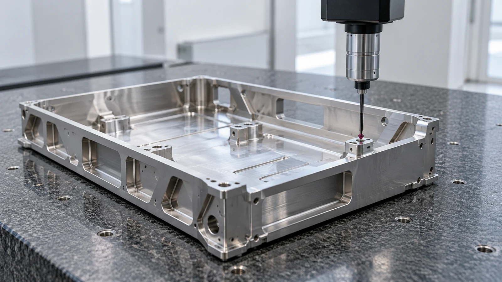
Consider how the tray will be measured. A flatness requirement across a large thin panel may require a defined support condition. A hole pattern may be checked relative to the spacecraft interface datums. A coating thickness or coverage characteristic may require process records or a separate acceptance method. Do not use one measurement to claim unrelated performance.
If the tray is delivered as an assembly, document the configuration, component revisions, and any controlled torque or joining process references. The battery itself may have separate handling and acceptance controls. Keep those records linked to the relevant configuration without implying that the machine shop performed battery qualification.
A practical release checklist
- Controlled model, drawing revision, material and temper.
- Battery and spacecraft mating interfaces, locating datums, and fastener access.
- Load-bearing features and program-approved retention requirements.
- Thermal contact or isolation requirements and any electrical keep-outs.
- Finish, coating, liner, cleanliness, and masking requirements.
- Critical-to-fit characteristics, inspection method, and finished-state acceptance.
- Quantity, prototype or flight-build status, traceability, and packaging expectations.
A satellite battery tray is ready for procurement when its mechanical job is clear and the battery-owned requirements are properly referenced. Early coordination between structural, thermal, electrical, battery, manufacturing, and quality teams reduces redesign around a part that otherwise appears deceptively simple.

