


A satellite radiator panel is part of the spacecraft’s thermal-control architecture: it provides a surface and structural interface through which the system rejects heat to space. It may also support equipment or contribute to the spacecraft structure, depending on the design. That role makes it easy to confuse a radiator panel with a cold plate or a conventional heat exchanger. They may belong to the same thermal system, but they solve different physical and manufacturing problems.
This guide approaches the panel from a part-manufacturing and procurement perspective. It does not size a radiator or predict spacecraft temperatures. Thermal analysis and the responsible design authority determine heat load, view factors, coatings, allowable distortion, and qualification. The manufacturing team needs that design context to make the part reproducible.
Keep the panel boundary clear
A radiator panel rejects heat from a spacecraft surface; a cold plate transfers heat from a component into a fluid loop or another thermal path, and a heat exchanger transfers heat between media or systems. A single spacecraft may use all three. Their interfaces can be connected, but a manufacturing article should not treat them as interchangeable terms.
The distinction matters when defining procurement scope. A radiator may include a structural substrate, thermal-control coating, embedded or attached heat transport hardware, equipment mounting features, and local reinforcement. A cold plate may instead prioritize channels, pressure boundaries, ports, and leak verification. An aircraft heat exchanger has its own fluid and structural requirements. Cross-linking these subjects is useful only when the reader needs to understand the larger thermal chain.
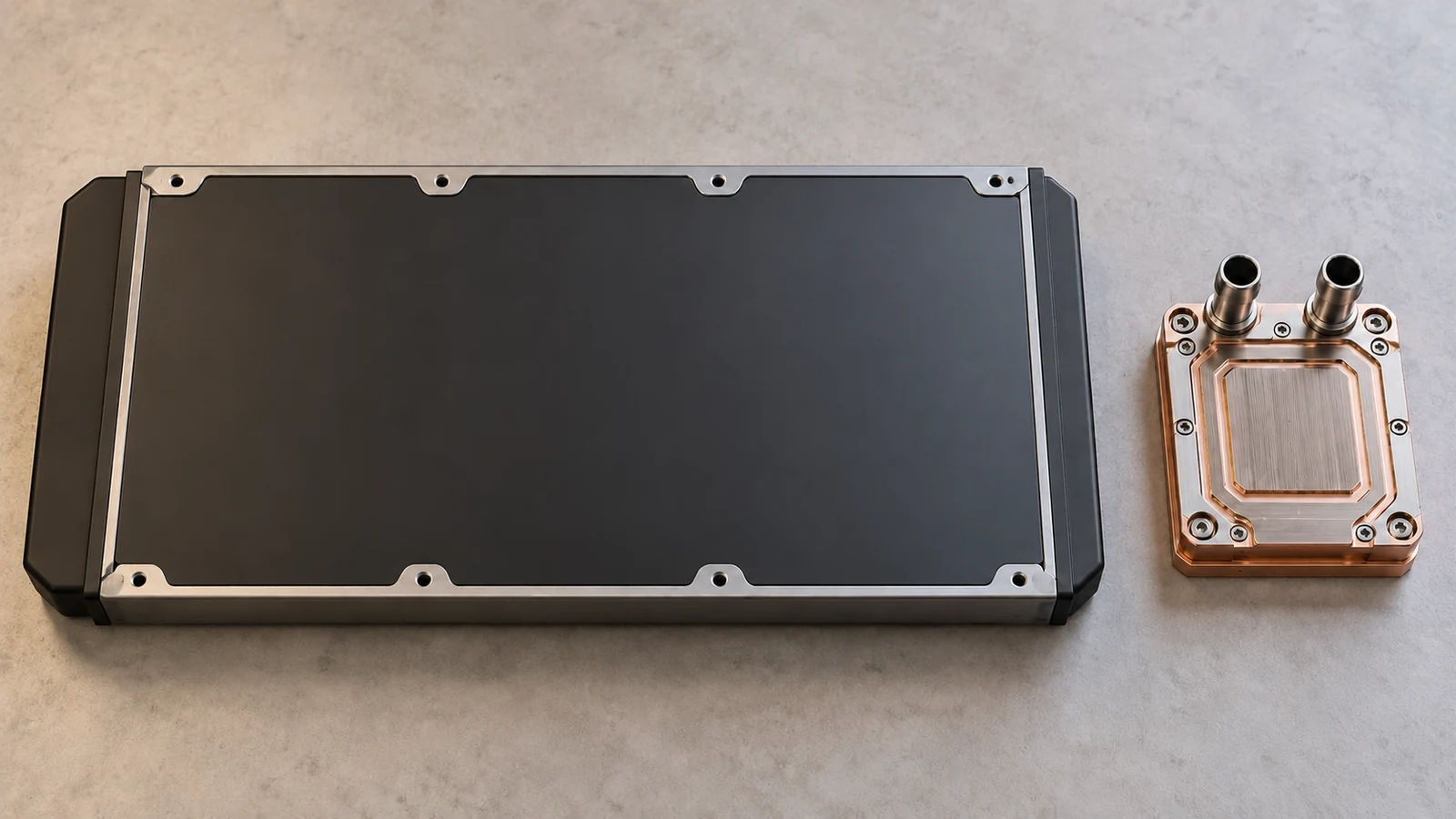
For a liquid-channel design, see the site’s aerospace cold plate design guide. This page stays focused on the spacecraft radiator panel’s structural and surface-manufacturing questions.
For broader program context, see the aviation and aerospace prototyping page; the radiator drawing still needs to define its own functional thermal boundary.
Read the panel architecture before choosing a process
Radiator panels can be built as plates, sandwich structures, integrated panels, or assemblies with heat pipes or other thermal hardware. A composite face sheet, metallic panel, bonded core, or embedded element changes the manufacturing route and inspection plan. The exact architecture is mission-specific; a manufacturing supplier should not infer it from the phrase “satellite radiator.”
Start by identifying whether the panel carries equipment loads, acts as a sidewall, provides a thermal view surface, or combines those functions. Then mark the critical interfaces: mounting inserts, edge rails, heat transport connections, electrical bonding points, and surfaces with controlled coating. A change to one interface can affect the panel’s structural, thermal, and assembly functions simultaneously.
Where a panel is lightweight and large relative to its thickness, deflection during handling or clamping can become a manufacturing concern. A fixture that holds the part flat for machining may not reflect how it behaves after release. Drawing notes should state the support or restraint condition for measurement and define any allowable deviation in the actual assembly condition.
Protect mounting and thermal interfaces
Mounting pads and inserts should be located from the panel’s controlling datums, not from an assumed “flat enough” face. If the equipment interface requires a pattern or plane, specify how it relates to the panel perimeter and thermal surface. For bonded constructions, clarify which faces are bonded, where adhesive fillets or edge closeouts are permitted, and which surfaces remain open for inspection.
Thermal interfaces can be sensitive to coating, surface preparation, flatness, and contact pressure. A supplier needs the specified finish and masking requirements before quoting, since a post-machining coating can change dimensions or make an electrical bonding point nonconductive. Do not invent a universal emissivity, coating thickness, or flatness value: these depend on thermal analysis, coating specification, and assembly design.
If the panel uses heat pipes or embedded thermal hardware, define the boundary between the panel supplier and the thermal-system supplier. Include connection locations, keep-out zones, joining restrictions, proof-test responsibilities, and inspection records. These are system-interface decisions, not generic CNC notes.
Plan fabrication around flatness and handling
For a monolithic metal panel, machining may create pockets, mounting lands, ribs, or local reliefs. The process plan must balance weight reduction with support during cutting. Deep pockets and thin residual webs can move after material removal, particularly if clamping or tool forces are uneven. A staged roughing and finishing approach can help, but the actual sequence should be proposed against the material condition and part geometry.
For a sandwich or bonded panel, process planning must protect the core and bond lines. Cutting, drilling, deburring, and edge finishing should avoid crushing or delaminating the structure. Hole locations for inserts and mounting hardware need a clear relation to the final datum. If bonded inserts are installed, define whether the supplier supplies them, what cure and inspection records are required, and how repaired or reworked locations are handled.
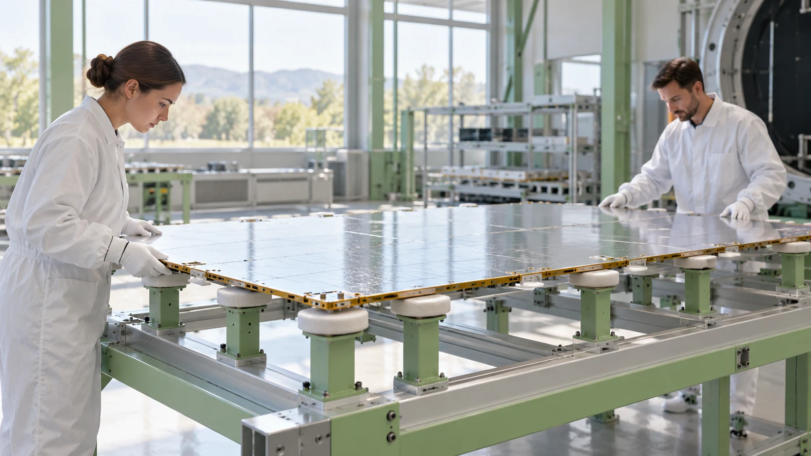
Handling is part of process design. Large thin panels may need lifting points, protective covers, or dedicated nests between operations. Support points used in machining and inspection should not create local dents or distortions. The broader aerospace manufacturing processes overview can help compare machining and sheet-metal operations when the panel includes mixed construction.
Treat surface finish as a functional requirement
The radiator’s exposed surface may carry a thermal-control coating or finish selected by the thermal team. The process must preserve the specified condition without contaminating, scratching, or masking the wrong area. A supplier needs the coating specification, surface preparation, protected zones, and inspection criteria—not just a note that the panel is “black” or “high emissivity.”
Bonding and electrical grounding can impose competing surface requirements. A painted or coated face may serve thermal performance, while a separate bare-metal interface may be necessary for electrical continuity or bonding. The drawing should identify these zones and their edges. If finish thickness affects a fit, show whether the dimensions apply before or after coating.
Review finish decisions with the authorized design and thermal engineers. The aerospace surface-treatment overview can orient the manufacturing discussion, but it is not a substitute for the part-specific approved coating and cleanliness requirements.
Build a verification plan from the drawing
Inspection may include overall envelope, flatness under a stated support condition, insert locations, hole patterns, bonded features, coating coverage, and records for special processes. Not every characteristic needs the same measurement method. A CMM can document feature position; a visual inspection may confirm surface condition; a bond inspection or thermal-system test may belong to a separate qualified process. Define responsibility and acceptance evidence for each.
For assemblies with thermal hardware, dimensional inspection does not prove heat-rejection performance. Likewise, thermal analysis does not prove that the machined mounting pattern will assemble. Keep component conformity, thermal-system verification, and spacecraft-level qualification as distinct steps, with traceable handoffs between them.
A quote package should identify the product definition revision, material and core details, coatings, interface drawings, quantity, and inspection records. If prototype panels are being built to examine fit or packaging, label that purpose. Do not infer mission readiness from a prototype that has not completed the program’s verification process. The aerospace inspection guide can help structure the evidence plan.
Frequently asked questions
Is a satellite radiator panel the same as a cold plate?
No. A radiator panel provides a surface for heat rejection, while a cold plate typically transfers heat into a fluid or another thermal path. They can work together in one system but have different interfaces and verification needs.
Can a panel’s coating be selected by the machine shop?
No. Coating performance and surface preparation are part of the controlled thermal and structural design. The shop can review manufacturability and quote the specified process, but design approval belongs to the responsible authority.
How should panel flatness be inspected?
The drawing should define the datum, support points, and restraint condition. A large thin panel can measure differently when free-state than when clamped, so inspection must use the state relevant to the requirement.
Does dimensional inspection verify thermal performance?
No. Dimensional inspection verifies specified geometry. Thermal performance requires the analysis and tests established by the program’s verification plan.

