


Exporting digital designs with incorrect mathematical definitions frequently causes severe machining errors and surface defects on finished physical parts. Tooling designers require seamless vector geometries to generate precise multi-axis CNC toolpaths and compute injection mold shrinkage offsets. Sourcing files that preserve mathematical curves prevents manufacturing systems from interpreting smooth circles as faceted, blocky surfaces. Sourcing the right engineering files from the start protects project timelines and maintains low development expenditures.
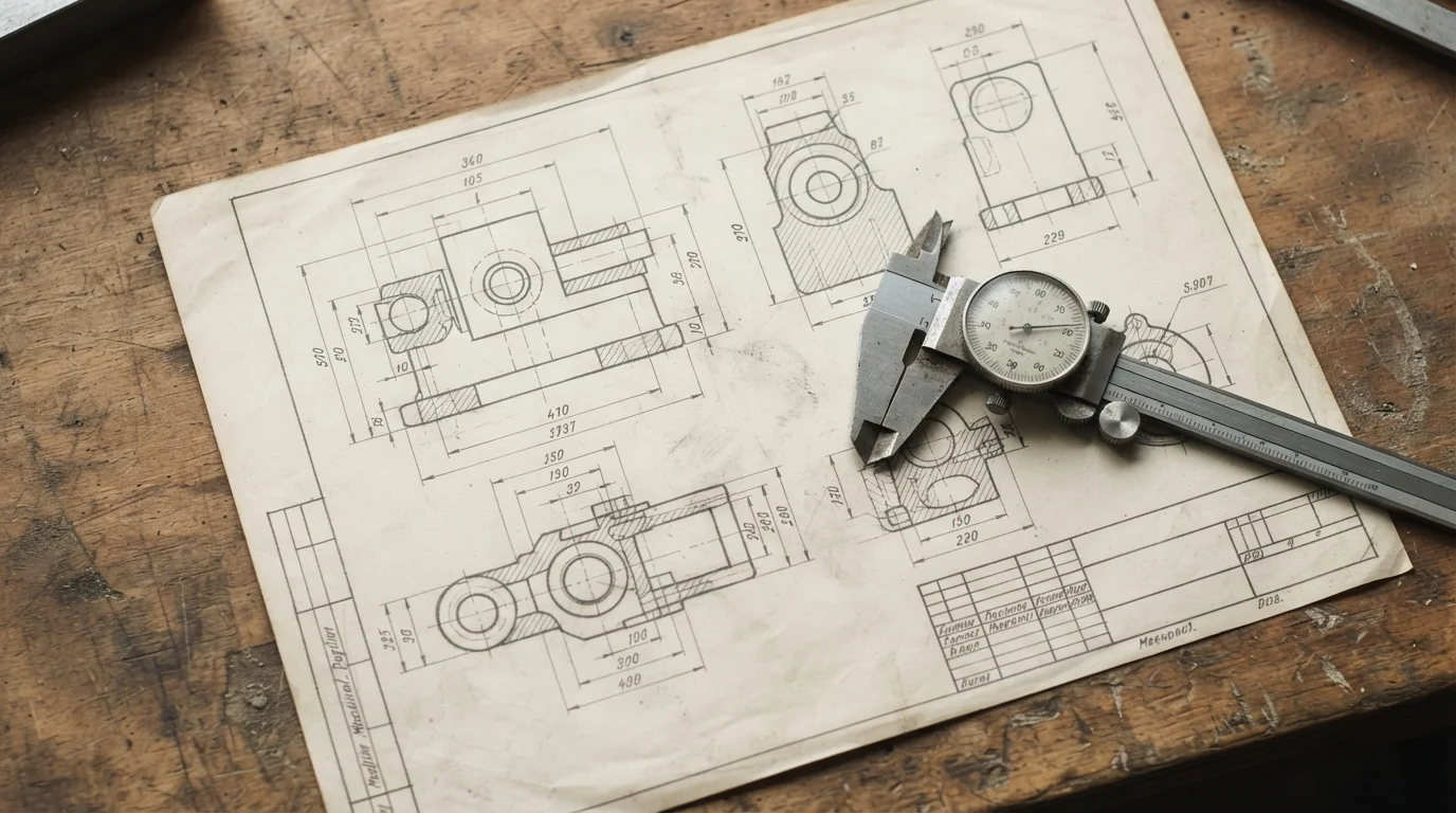
Successful implementation of rapid prototyping design principles requires a deep understanding of standard vector formats versus faceted mesh exports. Product engineers often make the mistake of sending raw polygonal meshes for high-precision milling or rapid tooling, causing immediate data translation blocks. Subtractive cutting tools cannot read flat triangle tessellations to carve organic curves with micro-tolerances. Resolving data definitions early ensures that factory teams can execute 24-hour free DFM reviews and provide accurate manufacturing quotes quickly.
Mechatronics designers choose neutral vector standards like STEP or Parasolid to maintain complete geometric control when sharing confidential hardware layouts. Industrial quality systems run under strict ISO 9001 and ISO 13485 guidelines to secure absolute traceability, making clean engineering files essential. Standard coordinate measuring machines verify sub-micron clearances by comparing physical dimensions against the original mathematical CAD boundaries. Safe file transmission systems shield proprietary intellectual property throughout every stage of fabrication.
Table of Contents
1. Mathematical Splines versus Faceted Mesh Tessellation
2. Choosing STEP and Parasolid over Rigid STL Files
Mathematical Splines versus Faceted Mesh Tessellation
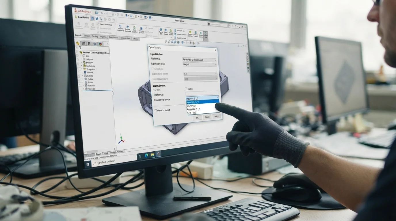
Question: Why are STL files unsuitable for high-precision CNC machining? STL files translate smooth mathematical surfaces into flat polygonal triangles, stripping away the micro-dimensional details required to generate clean subtractive toolpaths.
Selecting the correct 3d cad formats for rapid prototyping requires understanding the difference between NURBS splines and tessellated polygonal meshes. Non-Uniform Rational B-Splines (NURBS) define curves mathematically, preserving perfect circles and complex freeform shapes regardless of scale. Tessellated formats like STL slice these perfect curves into thousands of flat triangles, permanently stripping away the smooth boundary information. Machining a faceted STL file on a CNC mill results in blocky, stepped surfaces that ruin critical cosmetic show faces.
Exporting meshes with low resolution creates visible chordal errors, making holes look like hexagons rather than smooth circles. Tooling specialists must manually rebuild these faceted features in CAD to generate clean toolpaths, which increases lead times and setup costs. Designers must export native mathematical surfaces to allow CNC cutters to slide smoothly along programmed paths without chatter. Preserving mathematical curves ensures that physical mockups exhibit retail-grade surface smoothness after fine bead-blasting.
FDM and SLA 3D printers read faceted meshes easily because additive software slices polygons into horizontal layers to build parts sequentially. CNC milling and rapid injection molding, however, rely on continuous coordinate vectors that require real mathematical boundaries. Sourcing native vector formats protects overall part dimensional repeatability, ensuring interlocking features mate together seamlessly. Engineers protect launch schedules by matching file formats with specific manufacturing capabilities.
Choosing STEP and Parasolid over Rigid STL Files
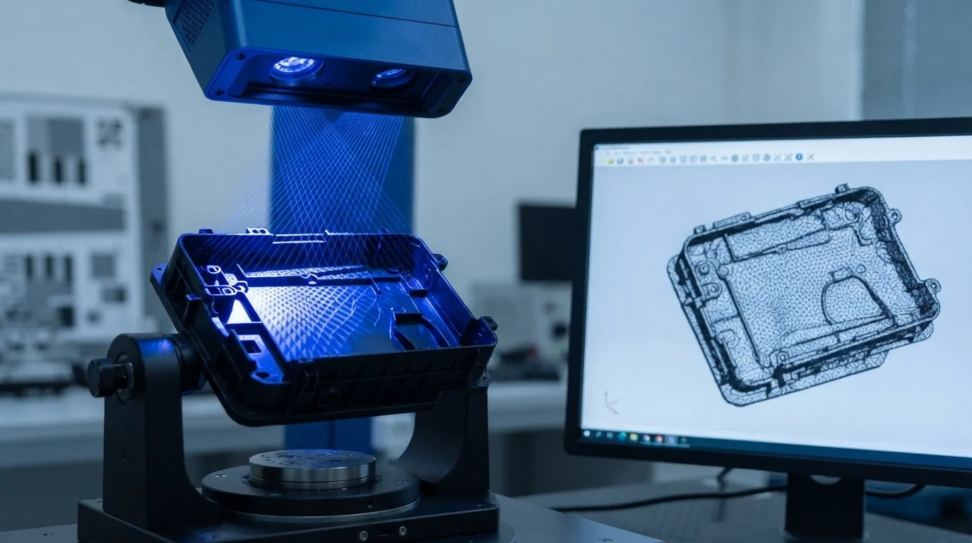
Question: What is the premier neutral file format for CNC machining quotes? STEP (.stp or .step) represents the industry standard for neutral vector data transfer, preserving complete 3D geometric structures flawlessly.
Neutral file formats allow engineers to transfer complex 3D CAD files between different CAD systems without losing critical feature histories. STEP files represent the global gold standard for vector data exchange, maintaining exact mathematical boundary representations (B-rep). Parasolid files (.x_t) also provide outstanding compatibility, particularly when working with Siemens-based solid modeling platforms. Sourcing these neutral formats guarantees that factory teams can inspect internal rib thicknesses and draft angles under dynamic simulators.
IGES represents an older neutral format that occasionally suffers from loose trimming curves, leading to broken surface shells when imported. Modern CNC machinists prefer STEP or Parasolid files because they preserve solid bodies cleanly, avoiding open-sheet geometry defects. This table compares baseline capabilities across standard data transfer formats used during developmental cycles:
| File Format | Mathematical Definition | Best Manufacturing Use | Feature Preservation Quality |
|---|---|---|---|
| STEP (.stp) | Exact NURBS curves / solid bodies | CNC milling, rapid injection tooling | Excellent (retains closed solids, surface data) |
| Parasolid (.x_t) | Exact NURBS / solid kernels | Multi-axis machining, complex gears | Outstanding (retains native solid structures) |
| STL (.stl) | Faceted polygonal triangles | SLA/SLS 3D printing, rapid mock-ups | Low (strips solids into flat facets) |
Sourcing appropriate 3d cad formats for rapid prototyping protects development budgets by eliminating human conversion errors during tool design. Jucheng Precision operates a fully equipped manufacturing facility containing 150+ CNC machines, including 25 high-precision 5-axis Haas/Mazak machines. Advanced multi-axis milling setups read mathematical STEP boundaries flawlessly, executing intricate geometries with micron-level coordinate repeatabilities. Sourcing native solid bodies prevents dimensional discrepancies during final assembly runs.
Combining 3D CAD Formats with Detailed 2D Blueprints

Question: Why are 2D PDF drawings required alongside 3D CAD files? 3D files define overall shape, but 2D drawings specify critical tolerances, threaded hole locations, and specific surface finish requirements.
Relying solely on 3D solid models is a common cause of dimensional delays because standard files cannot define custom thread taps or critical fit tolerances. Sourcing detailed 2D PDF drawings alongside your 3D files provides machinists with the legal specifications needed to calibrate their spindles. Tolerances like ±0.01 mm for bearing bores or specific surface roughness values must be annotated clearly on 2D layouts. Scribing tap sizes, thread pitches, and surface anodizing requirements on PDF blueprints guarantees complete engineering compliance.
Coordinating both 2D and 3d cad formats for rapid prototyping ensures that our QA inspectors can verify finished parts using automated CMM equipment. Jucheng Precision delivers comprehensive 24-hour free DFM reviews to optimize wall thicknesses, parting lines, and thread depths before cutting metal. Sourcing high-fidelity pre-production parts within 4 to 15 days helps mechatronics groups hit aggressive launch schedules safely. Operating under a strict no-MOQ policy enables engineering teams to refine customized hardware variations without paying heavy initial tooling costs.
Flexible manufacturing programs allow design teams to transition seamlessly from low-volume prototypes to full-scale injection molding. Factory teams utilize specialized rapid tooling molds to deliver injection-molded components quickly. Protecting your data remains our top priority, and we execute mutual non-disclosure agreements (NDAs) before reviewing design files. Sourcing your prototypes from Jucheng Precision guarantees your designs are manufactured to exact mathematical specifications safely.
Frequently Asked Questions (FAQ)
Which neutral file format is better, STEP or IGES?
STEP represents a far superior format compared to IGES because it preserves solid-body boundaries and feature trim surfaces cleanly. IGES often suffers from broken faces and open sheets when imported, requiring manual rebuilding before toolpath generation.
Can you generate a CNC quote from an STL file?
Generating quotes from STL files is possible for simple geometries, but the quote remains a rough estimate because the file lacks exact dimensions. Engineers must provide STEP or Parasolid files to secure firm, high-precision machining commitments.
Why are 3D CAD files scaled before mold tool fabrication?
Mold designers scale up 3D files by approximately 0.2 percent to compensate for natural polymer shrinkage as the plastic cools inside the cavity. Scaling solid models mathematically ensures the finished molded parts match the target blueprint dimensions exactly.

