


3D printing for automotive prototypes works when the printed part is selected to answer a specific development question. It can compress iteration time for package models, airflow paths, clips, housings, interior controls, lighting studies, assembly aids, and even selected metal components. It cannot make every prototype production-representative simply because the geometry is accurate.
The engineering task is to choose the smallest, fastest build that provides trustworthy evidence for the next decision—and to know when another process should take over.
Prototype decision sequence
Write the Engineering Question Before Sending the File
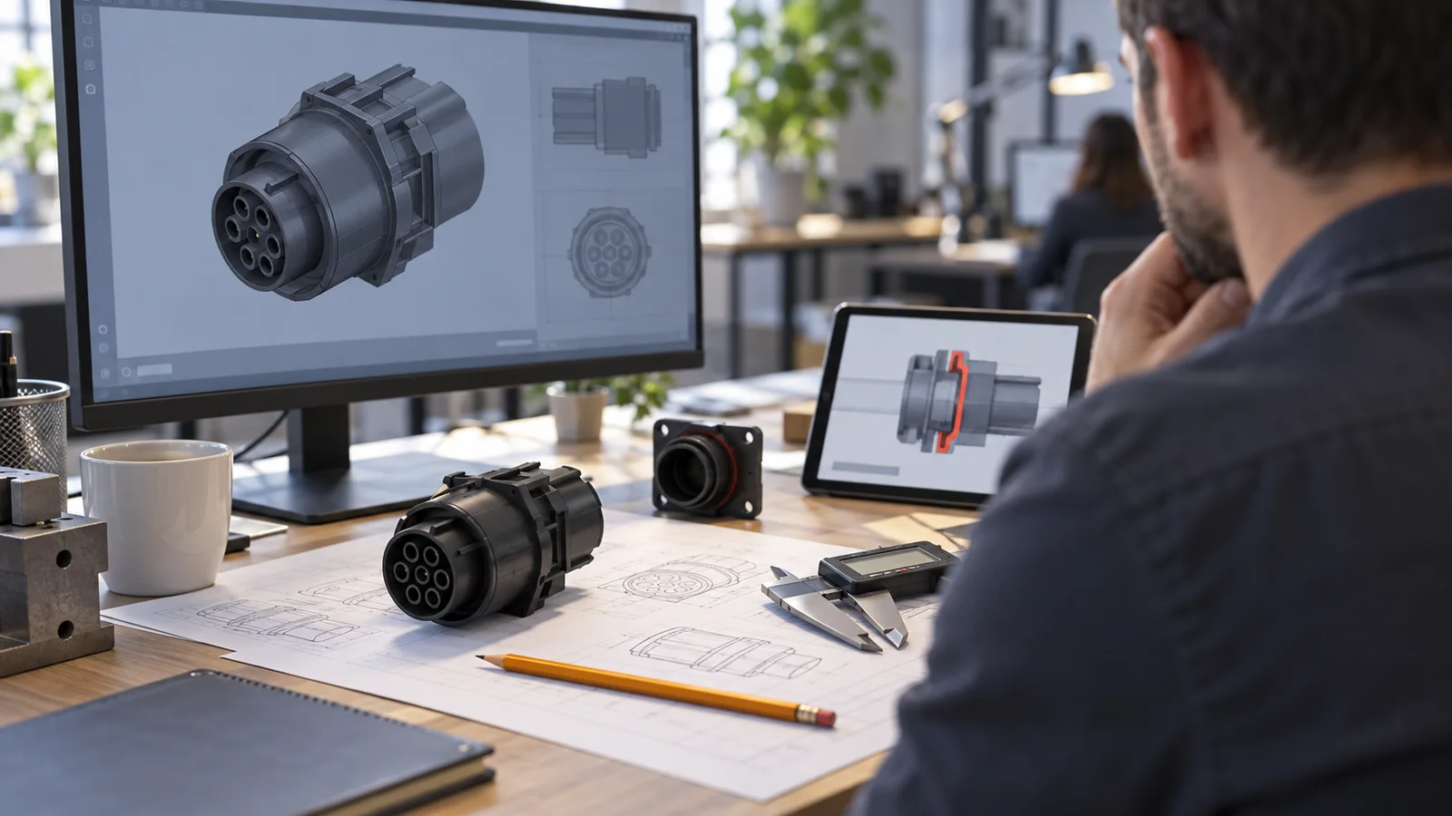
A request such as “print this housing” leaves critical choices hidden. A better request states the decision: verify connector access, compare latch forces, check an air duct in the package, review surface proportions, install sensors on a test vehicle, or obtain stakeholder approval. That sentence controls material, printing process, build direction, finishing, quantity, and inspection.
Define what the prototype must represent and what it may simplify. A package model may use a neutral color and reduced internal detail. A clip test needs the actual root geometry and a material with relevant flexibility. An airflow model needs a sealed internal path. A presentation part may need smooth surfaces but not production strength.
Every child article in this cluster should link once to the main automotive manufacturing page. Here, that link establishes the industry context while the article stays focused on the role of additive manufacturing in prototype decisions.
One Word—Prototype—Hides Four Different Jobs
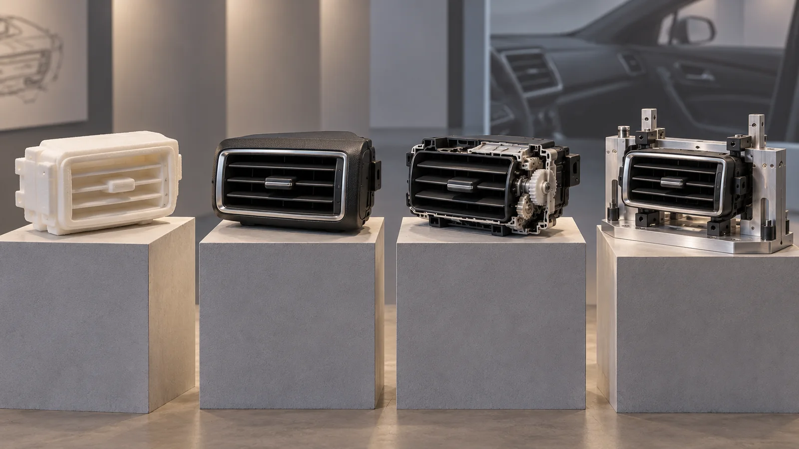
Package prototype
This build checks volume, clearance, reach, service access, and interference. Speed matters more than cosmetic finish. Large parts can be hollowed, sectioned, or assembled from modules, provided the datum structure and controlled interfaces remain stable.
Appearance prototype
This build communicates form, proportion, color, gloss, texture, lighting, and perceived quality. It may require sanding, primer, paint, film, transparent elements, decals, or soft components. Dimensional inspection should occur before heavy finishing changes edges and gaps.
Functional prototype
This build carries load, moves, seals, clips, routes fluid or air, houses electronics, or survives repeated handling. Material behavior and build orientation become central. A functional print should include a written limitation statement because printed properties may be anisotropic and process-dependent.
Process-learning prototype
This build investigates assembly sequence, fixture access, error proofing, inspection, packaging, or production handling. The prototype may be a surrogate part, a drill guide, an assembly nest, or a checking aid rather than the vehicle component itself.
Technology Choice Is Also an Orientation Decision
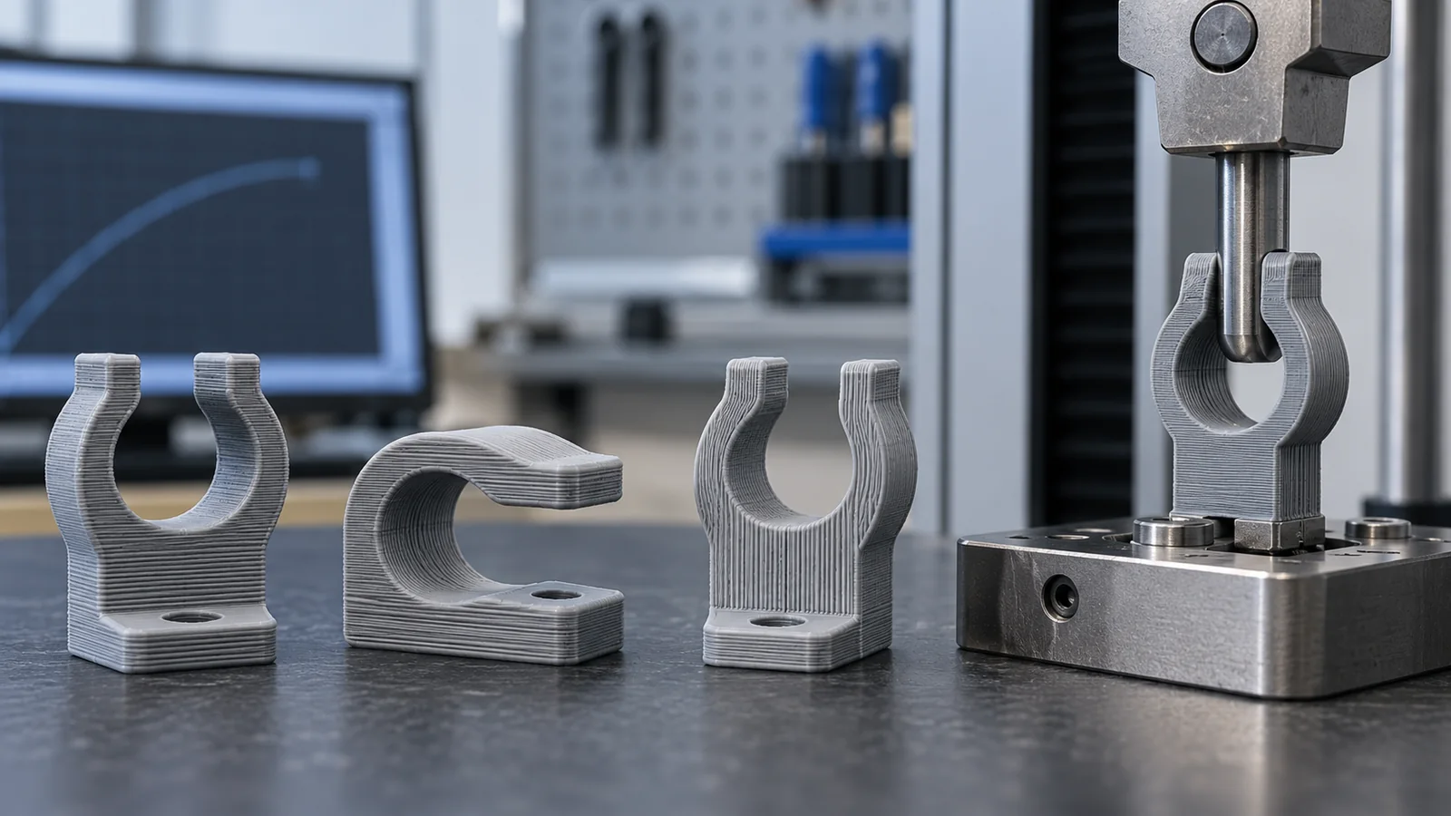
FDM offers rapid, economical models and useful engineering thermoplastics, especially for larger parts and fixtures. SLA provides fine features and smooth surfaces. SLS and MJF support complex durable polymer components without conventional support structures. Material jetting can combine colors or material responses. Metal powder-bed fusion supports complex high-value parts where conventional routes cannot easily provide the geometry.
Orientation changes surface quality, support contact, dimensional behavior, build time, and strength. A clip printed across layers may fail at a load that the same geometry survives when oriented along the stress path. A circular bore may become less round in one orientation. A visible face may carry support witness or stair stepping.
| Decision | First priority | Evidence to record |
|---|---|---|
| Package fit | Datum accuracy and assembly stability | Measured gaps, interference and revision |
| Clip or hinge | Material response and orientation | Force, cycles, failure location and temperature |
| Appearance | Surface preparation and visual standard | Color, gloss, texture and viewing condition |
| Air or fluid path | Internal geometry and sealing | Leak state, flow condition and pressure |
The broader automotive 3D printing overview can compare process families. This page should remain a selection guide for prototype programs, with orientation and evidence built into the decision.
The Best Prototype Is Sometimes Not Printed
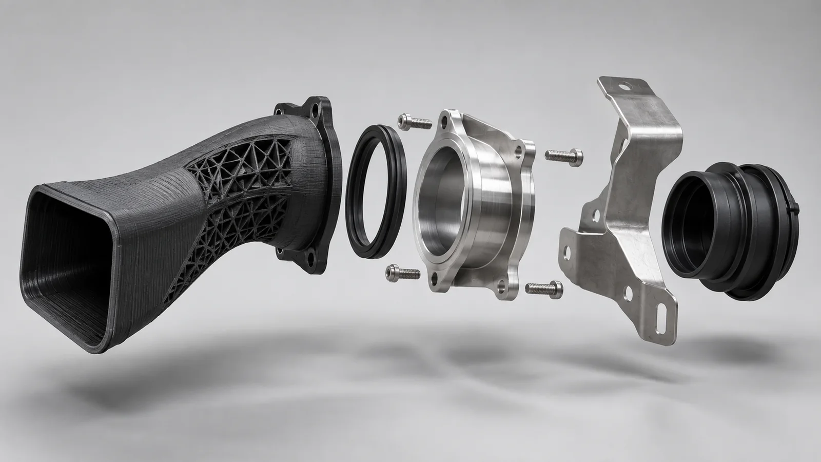
CNC machining may be better for precise bores, flat sealing interfaces, threaded features, or parts that must be made from a specified engineering plastic or metal. Sheet metal is more representative for brackets whose stiffness depends on gauge, bend radii, hems, and formed beads. Vacuum casting may be better for a matched small batch with molded appearance. Rapid tooling may be necessary when molding behavior itself is the question.
Hybrid prototypes often provide the strongest evidence. A printed duct can use CNC-machined flange inserts. A printed housing can accept real connectors and sheet-metal brackets. A display model can combine clear SLA lenses, painted shells, elastomer buttons, and machined trim. The goal is not to maximize printed content; it is to minimize uncertainty.
Cost comparisons should include finishing, inserts, assembly, inspection, failure risk, and schedule—not only machine price. A cheap build that breaks during installation or answers the wrong question can delay the program more than a deliberately chosen hybrid.
Use Short Builds to Create a Fast Evidence Loop
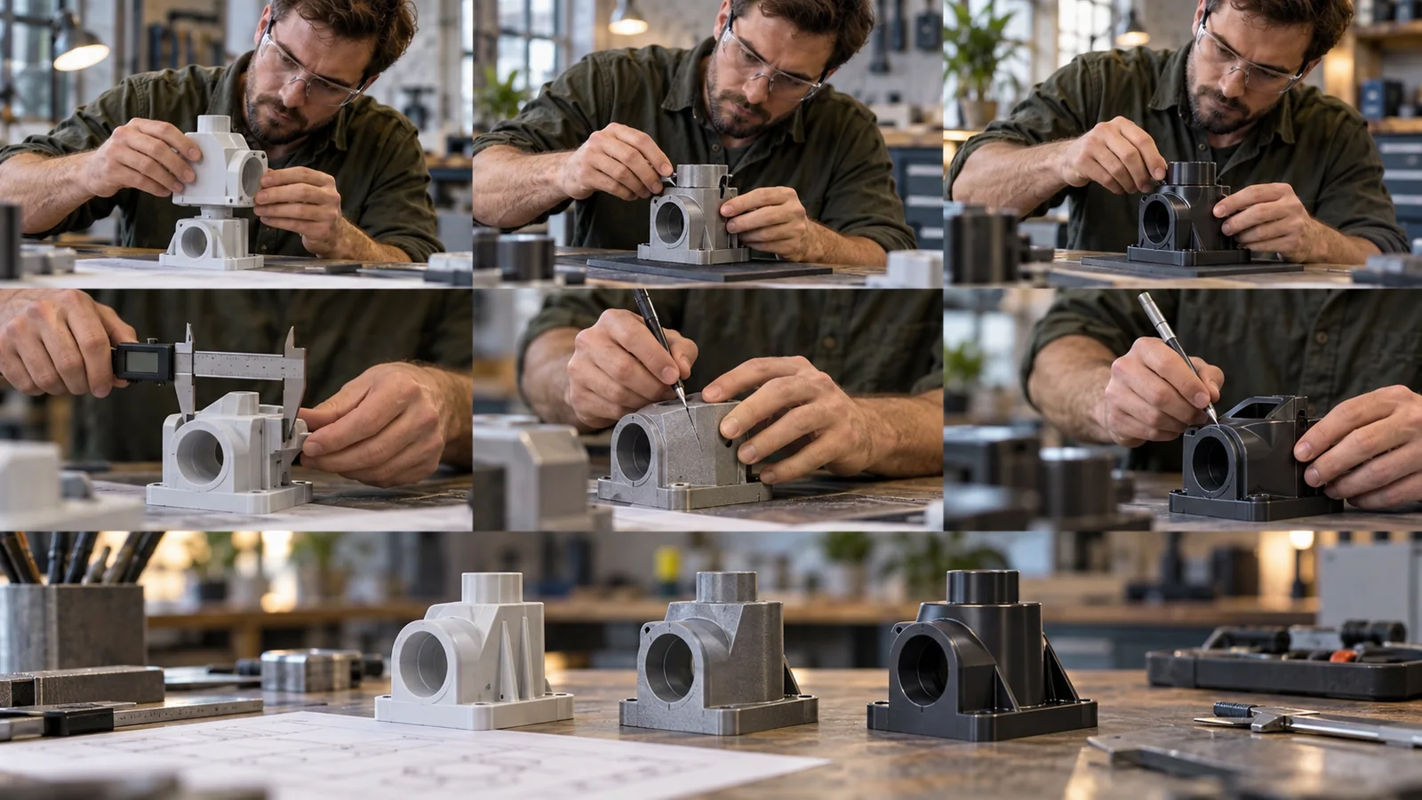
Freeze a revision, state the hypothesis, print the smallest representative geometry, inspect it, run the planned interaction, record the result, and update the model. That loop is more valuable than producing a fully finished vehicle-size assembly before the critical interface has been challenged.
Maintain configuration control. Mark the part with revision identification where practical, and store build orientation, material, process, finishing, and deviations. When several variants reach a workshop together, visual similarity can easily lead to conclusions being assigned to the wrong design.
Photographs are useful but insufficient. Record measurements, forces, cycle counts, leak conditions, temperatures, installation observations, and failure locations. A concise build report lets remote engineering, sourcing, and manufacturing teams use the prototype as shared evidence.
A Printed Success Still Needs a Production Bridge
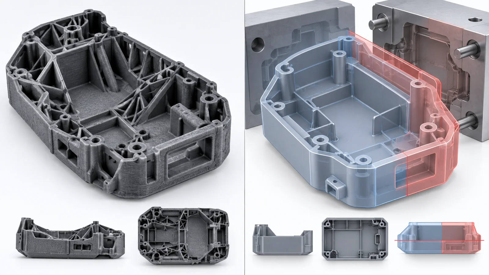
Before tooling release, translate printed geometry into the target process. Add molding draft, review wall transitions, replace print-only internal features, establish shutoffs, and plan gates and ejection. For sheet metal, restore bend allowances, tool access, and joining sequence. For die casting, review parting, overflow, ejector, machining stock, and porosity-sensitive zones.
The automotive rapid prototyping plan should make this transition explicit. Early prints discover layout problems; later builds increase material and process fidelity. The handoff is complete only when prototype findings have changed controlled CAD, drawings, specifications, and validation plans.
Jucheng Precision can combine additive manufacturing with CNC machining, molding, sheet metal, casting, finishing, inspection, and assembly. That cross-process view helps prevent a print-optimized design from reaching production unchanged.
Frequently Asked Questions

Is 3D printing suitable for functional automotive prototypes?
Yes, when the material, orientation, process, and test are matched. Functional prints can evaluate fit, motion, airflow, selected loads, clips, and assemblies. Production-level heat aging, fatigue, chemical resistance, crash behavior, and regulatory evidence normally require representative materials and processes.
How many prototype iterations are normal?
There is no universal number. Use iterations until the high-risk assumptions are resolved. Several small interface builds can be faster and cheaper than one complete build that reveals many unrelated problems at once.
Should every printed part be fully finished?
No. Finish only to the level needed for the decision. Cosmetic finishing adds time, cost, and dimensional change. Engineering samples should often remain uncoated so cracks, layer effects, and interfaces stay visible.
What files should be sent for an automotive prototype?
Provide 3D geometry, drawings for critical interfaces, target quantity, material intent, expected test, neighboring-component data, surface requirements, revision identification, and a statement of the question the prototype must answer.

