


Aerospace Design: DFM Principles for Flight-Critical Parts
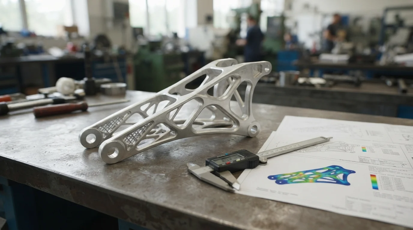
Designing flight-critical airframe components, satellite mounting brackets, and propulsion housings requires embedding manufacturability principles into early 3D CAD models before cutting metal billet. When aerospace mechanical engineers draft complex structural components, adhering to rigorous aerospace design principles ensures that parts achieve maximum lightweighting while remaining machinable on standard multi-axis machine tools. Ignoring tool clearance, corner radii, and wall thickness ratios leads to cutter vibration chatter, excessive tool wear, and catastrophic spindle collisions during multi-axis machining.
Utilizing an experienced contract manufacturing partner ensures that high-strength AL7075-T6 aluminum spar caps, forged titanium (Ti-6Al-4V Grade 5) fittings, and heat-resistant Inconel 718 brackets transition smoothly from digital concepts into certified flight hardware. Let us examine the core geometric rules, pocketing ratios, and vibration damping protocols that govern compliant flight design.
Module 1 – Definition and Working Principles of Lightweight DFM Architecture
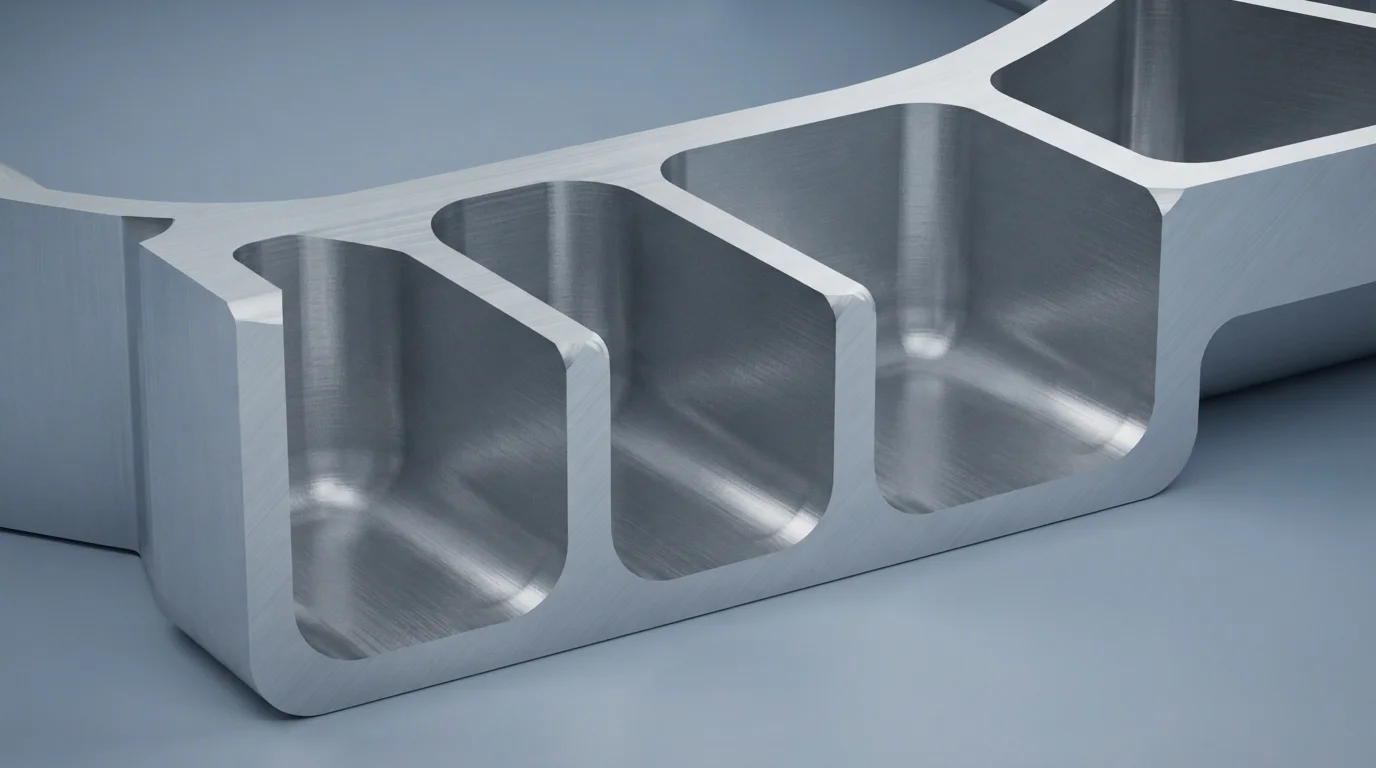
Design for Manufacturability (DFM) in aviation evaluates CAD geometry to ensure components can be milled efficiently, inspected accurately, and deployed reliably under severe dynamic g-forces. The working principle relies on matching internal pocket depths, corner radii, and web thicknesses to standard cutting tool aspect ratios. While basic components can be shaped via standard metal cutting, complex airframe structures demand specialized 5-axis CNC machining to carve asymmetric pockets without manual repositioning.
To execute a structured DFM protocol on flight-critical CAD geometry, mechanical designers could follow these practical steps:
- Pocket Depth and Fillet Matching: Design internal corner radii to at least 1/3 of the total pocket depth, allowing larger, rigid endmills to clear material without chatter.
- Wall Thickness Optimization: Maintain structural pocket walls and floor webs at a minimum of 1.0 mm to 1.5 mm to prevent cutting tool vibration and deflection.
- Tool Clearance Verification: Verify spindle head clearance in 5-axis CAM simulation to eliminate collision risks when cutting deep undercuts.
Module 2 – Core Application Scenarios Across Flight Subsystems
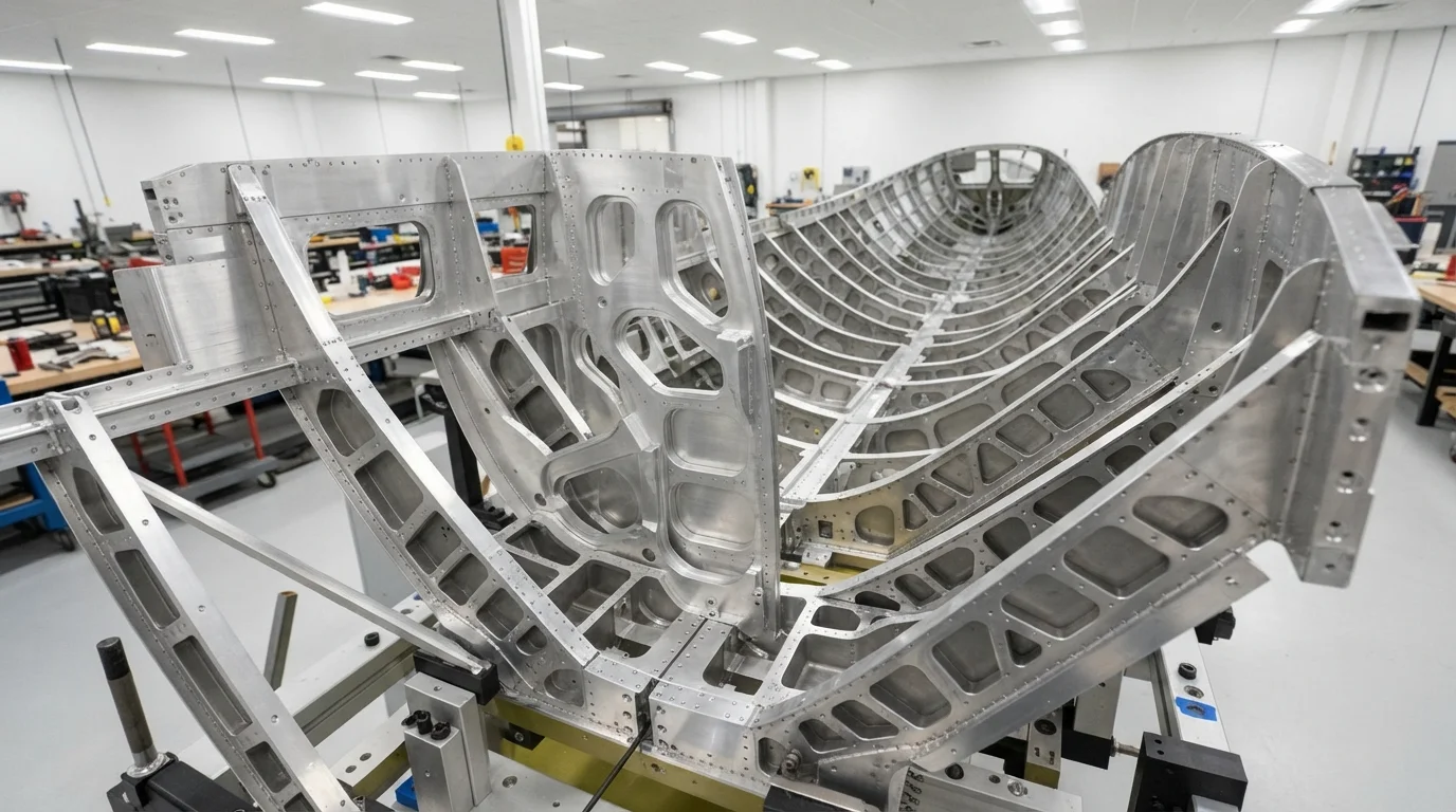
Applying specialized design rules is critical across airframe wing boxes, satellite payload interfaces, and jet engine nacelles where every gram of excess mass reduces operational range or payload capacity. When aerospace OEMs develop new airframe assemblies, applying proven aerospace design guidelines prevents structural stress concentrations and avoids expensive custom cutting tools. Discussions across aerospace engineering groups on Reddit and Facebook emphasize that standardizing corner radii across an entire airframe reduces multi-axis CNC machine hours by up to forty percent.
Primary application sectors include:
- Airframe Wing Ribs & Spars: Designing deep pocketed AL7075-T6 aluminum structures with continuous reinforcing ribs for optimal torsional stiffness.
- Satellite Payload Brackets: Engineering topology-optimized titanium and PEEK brackets designed to survive extreme rocket acoustic vibration during launch.
- Jet Engine Nacelles: Sculpting thin-walled Inconel and titanium air-intake cowlings featuring smooth aerodynamic airflow contours.
Module 3 – Key Selection Factors for Project Success

When specifying geometric features on aerospace CAD models, engineering teams must balance pocket wall thickness, internal corner radius sizes, and maximum aspect ratios. Evaluating these core parameters ensures your components are manufactured with high yield rates and minimum cycle times.
| Design Feature | Recommended Engineering Value | Primary Manufacturing Benefit |
|---|---|---|
| Pocket Wall Thickness | 1.0 mm to 1.5 mm minimum (Aluminum) / 1.5 mm+ (Titanium) | Prevents cutting tool vibration, chatter marks, and micro-deflection |
| Internal Corner Radii | Radius ≥ 1/3 of pocket depth (e.g., R5 mm for 15 mm depth) | Allows standard rigid endmills to run at high feed rates without breaking |
| Pocket Depth-to-Width Ratio | Maximum 4:1 depth-to-width aspect ratio | Eliminates the need for specialized long-reach cutters that induce chatter |
Module 4 – Installation and Maintenance Tips

Proper stress-relief heat treatment, progressive multi-axis roughing, and routine CMM verification safeguard structural flight parts throughout manufacturing and operational lifecycles. Protecting thin pocket walls from thermal warping ensures long-term airframe dimensional stability.
Key installation and maintenance tips include:
- Intermediate Stress Relief: Perform intermediate vacuum baking on deep-pocketed titanium and aluminum brackets between rough and finish milling to release internal stresses.
- Equalized Clamping Force: Utilize vacuum chucks or soft custom vise jaws during thin-wall finish milling to prevent mechanical clamping distortion.
- Surface Passivation & Anodizing: Apply Type III hard anodizing or Alodine chemical conversion coating to protect machined aluminum pockets from environmental oxidation.
Module 5 – Frequently Asked Questions (FAQ)
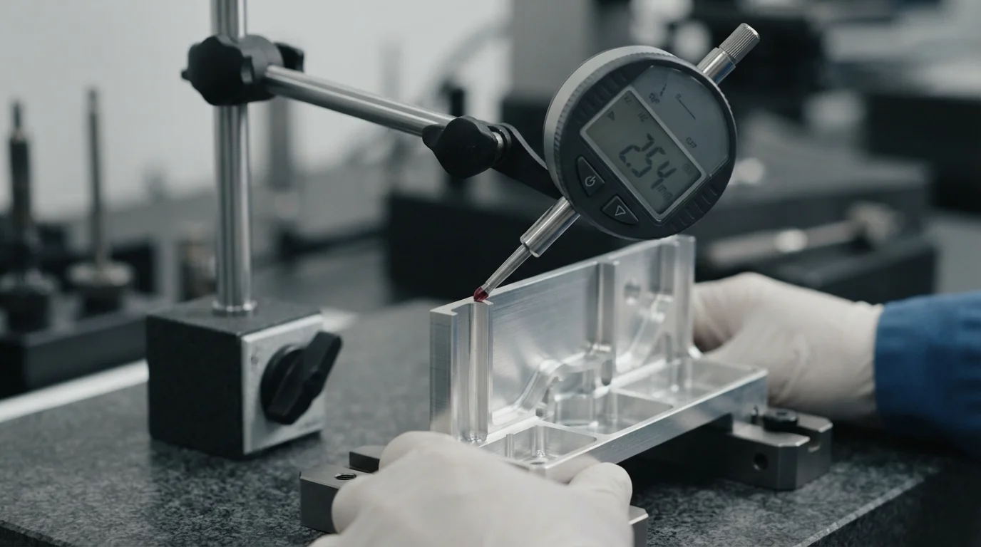
1. What is the minimum recommended wall thickness for machined aerospace aluminum?
The recommended minimum wall thickness is 1.0 mm to 1.5 mm for aluminum parts; walls thinner than 1.0 mm tend to vibrate under high-speed cutting, causing chatter and dimensional error.
2. Why are sharp internal 90-degree corners prohibited in aerospace pocket design?
Round rotating CNC endmills cannot cut sharp square corners without slow EDM operations, and sharp internal corners create severe stress concentrations that invite fatigue cracking.
3. How does internal corner radius sizing influence machining cycle time?
Designing corner radii slightly larger than standard tool radii (e.g., R6.5 mm for a 12 mm cutter) allows the tool to sweep smoothly through corners without pausing, cutting machining time by 30%.
4. How does 5-axis CNC machining prevent tool collision in complex aerospace parts?
5-axis machines tilt the cutting tool and workpiece simultaneously, allowing shorter, stiffer endmills to reach deep pockets without the spindle housing colliding with part sidewalls.
5. What causes thin-wall warping during aerospace machining and how is it prevented?
Residual stress release and cutting heat cause thin walls to bow; stepping down pocket depths evenly on both sides of a rib and applying intermediate stress relief prevents warpage.
6. How does Jucheng Precision assist with aerospace DFM evaluations?
Jucheng Precision provides automated 5-axis CAM toolpath simulation, wall thickness audits, corner radius optimization, and collision detection within 24 hours under AS9100 standards.
Module 6 – Why Choose JUCHENG for Your Project
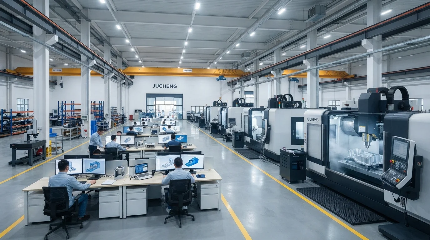
Achieving optimal lightweighting and uncompromised flight safety requires an experienced manufacturing partner with advanced multi-axis machining infrastructure. JUCHENG supports aerospace innovators by delivering comprehensive 24-hour free DFM reviews that analyze tool clearances, pocketing aspect ratios, and corner radii prior to cutting metal billet. Founded in Shenzhen in 2012 with an 8,000-square-meter facility in Dongguan, our factory houses 150+ advanced machines, including 25+ high-performance 5-axis Haas and Mazak milling centers [9.10].
Backed by ISO 9001, ISO 14001, ISO 13485, and IATF 16949 certifications, our engineering teams ensure that implementing compliant aerospace design principles achieves sub-micron accuracy, minimal buy-to-fly material scrap, and absolute batch consistency.
Ready to Optimize Your Aerospace CAD Design for 5-Axis Machining?
Upload your 3D models today to receive instant feedback, competitive pricing, and professional DFM analysis from our seasoned engineering experts. Let JUCHENG bring your complex designs to life with unmatched speed and reliability!

