


Aerospace Machining Tolerances: Micro-Precision Standards
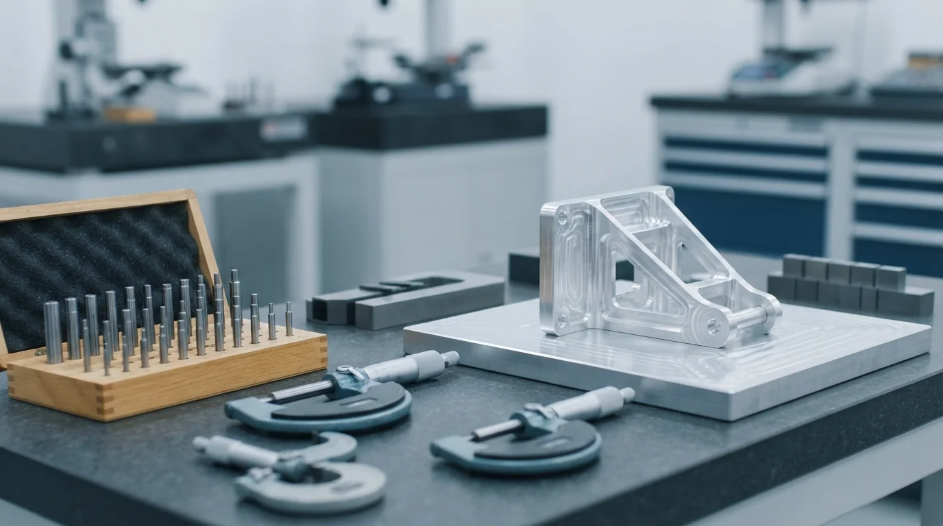
Operating flight vehicles across high-altitude sub-zero stratospheric conditions while managing extreme aerodynamic friction demands sub-micron mechanical alignment. When aviation engineering teams design landing gear pivots, jet fuel valves, or satellite propulsion manifolds, specifying realistic aerospace machining tolerances ensures leak-proof hydraulic seals and flawless dynamic articulation. Loose geometric limits invite high-altitude pressure leaks and structural vibration, while unnecessarily tight blanket callouts drive machining scrap rates upward.
Utilizing an experienced contract manufacturing partner ensures that structural AL7075-T6 aluminum airframe ribs, high-strength titanium (Ti-6Al-4V Grade 5) fittings, and heat-resistant Inconel 718 turbine mounts maintain dimensional stability under prolonged spindle cycles. Let us examine the micro-precision boundaries, thermal expansion controls, and CMM metrology verification protocols that govern flight hardware quality.
Module 1 – Definition and Working Principles of Sub-Micron Flight Precision
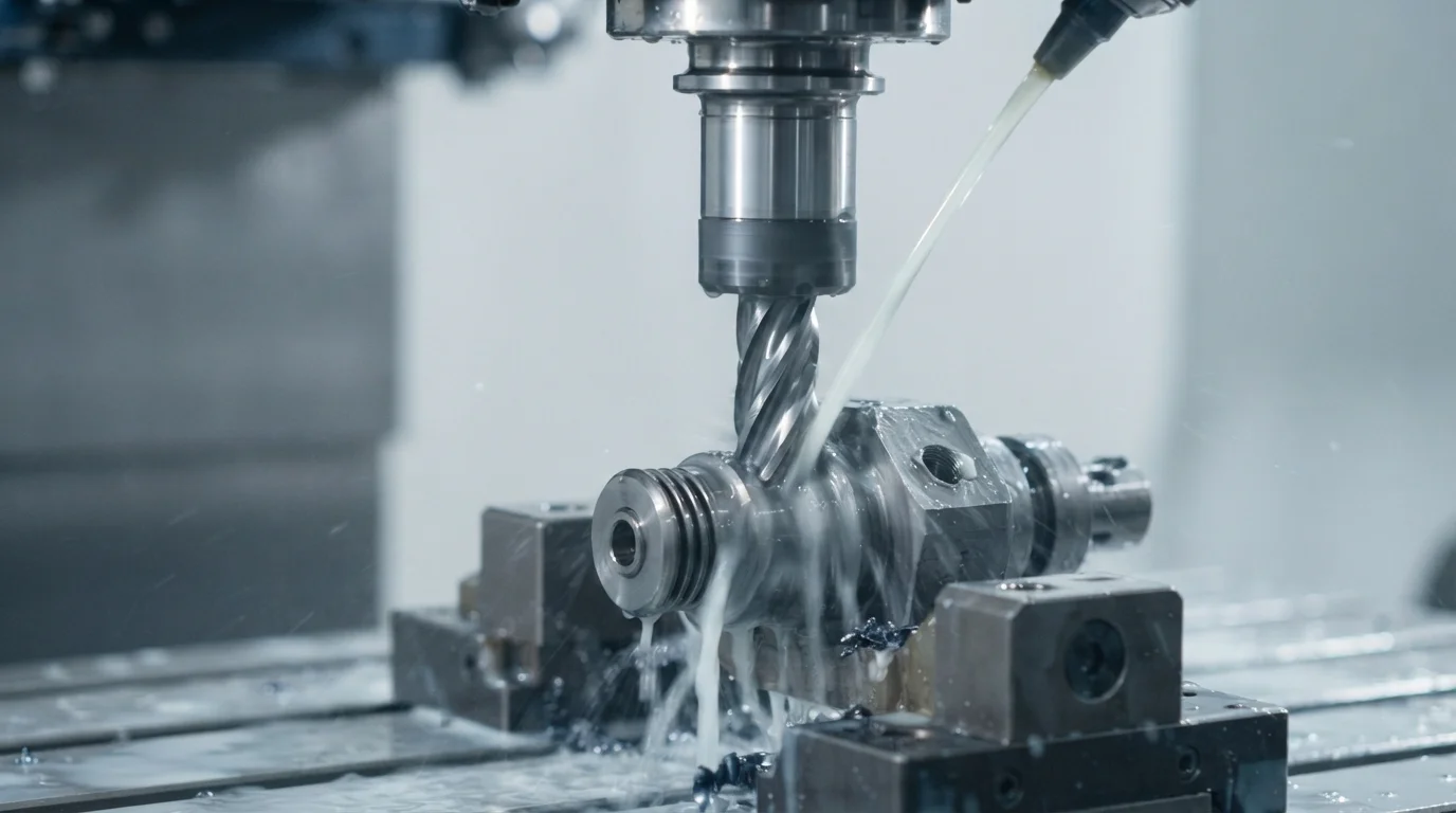
Geometric tolerancing in aviation manufacturing establishes the maximum allowable physical deviation from ideal digital CAD coordinates to ensure universal interchangeability and zero-failure flight operation. The working principle relies on ultra-rigid machine tool construction, direct-drive linear optical scales, and active real-time thermal drift compensation across all machine axes. While secondary covers can be formed via standard sheet metal techniques, mission-critical flight joints depend entirely on high-rigidity 5-axis CNC machining and climate-controlled toolroom execution.
To execute a structured micro-precision workflow on flight hardware, quality engineering teams could follow these practical steps:
- Functional Datum Mapping: Establish primary, secondary, and tertiary datum reference frames based on physical flight mounting interfaces.
- Thermal Compensation Control: Maintain workshop and metrology lab ambient temperatures at a strict 20°C (±0.5°C) to prevent thermal dimensional expansion during cutting.
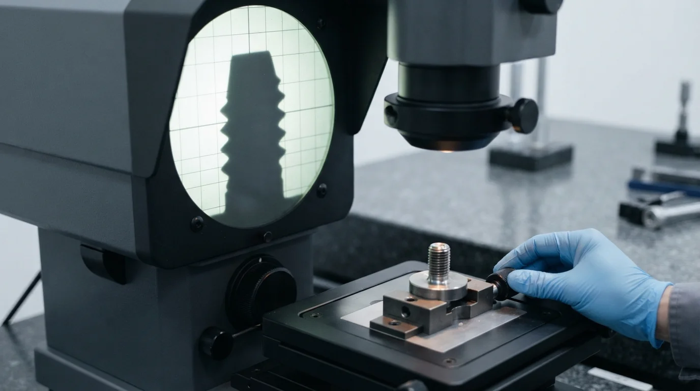
- Zeiss CMM Scanning Verification: Deploy continuous contact scanning probes to measure circularity, runout, and true position against 3D CAD master models.
Module 2 – Core Application Scenarios Across Mission-Critical Assemblies
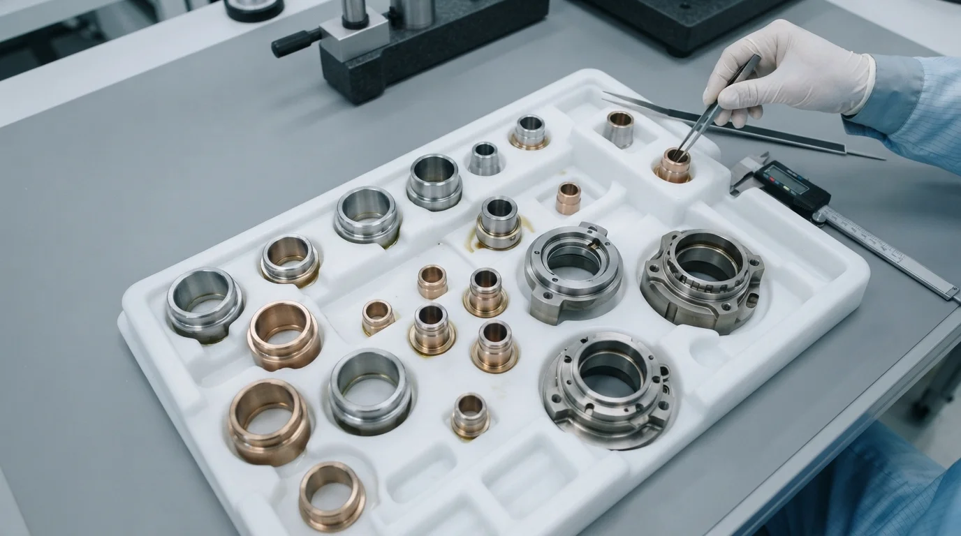
Maintaining tight dimensional limits is critical across flight control actuators, jet engine fuel nozzles, and satellite optical mounting payloads where micro-deviations cause hydraulic lockup or sensor distortion. When aerospace OEMs construct complex propulsion assemblies, managing tight aerospace machining tolerances guarantees flawless hydrodynamic flow and zero mechanical binding. Discussions across aerospace engineering communities on Reddit and Facebook emphasize that 5-axis CNC micro-milling combined with 100% CMM mapping is mandatory for flight-critical rotating assemblies.
Primary application sectors include:
- Hydraulic Flight Control Valves: Machining spool valve bores and sleeve housings from 17-4PH stainless steel with ±0.005 mm cylindrical tolerances.
- Landing Gear Actuator Assemblies: Turning high-strength titanium pivot pins, bearing sleeves, and hydraulic piston shafts with sub-micron runout limits.
- Turbine Rotor Interfaces: Milling Inconel 718 fir-tree blade root slots that require microscopic profile accuracy to secure turbine blades under high centrifugal forces.
Module 3 – Key Selection Factors for Project Success
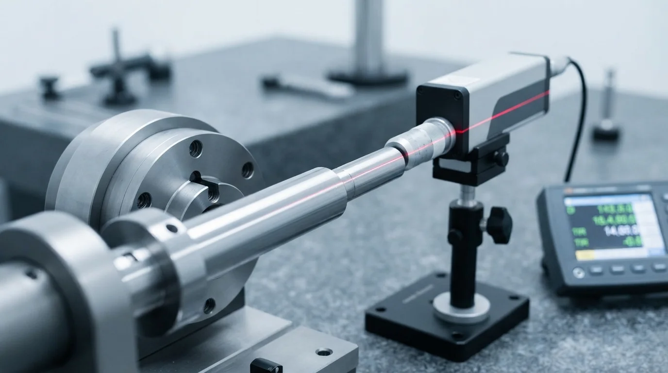
When specifying dimensional boundaries on aerospace blueprints, engineering teams must balance baseline structural limits against fine precision requirements. Evaluating these core parameters ensures your components assemble smoothly without binding or excessive machining costs.
| Tolerance Classification | Achievable Dimensional Range | Typical Aerospace Component Target |
|---|---|---|
| Standard Aerospace Class | ±0.025 mm to ±0.050 mm | Airframe wing ribs, fuselage bulkheads, structural bracket bodies |
| Precision Flight Class | ±0.005 mm to ±0.010 mm | Bearing bores, hydraulic spool valves, landing gear pivot pins |
| Micro-Positioning Class | ±0.002 mm to ±0.005 mm (Geometric true position) | Satellite optical sensor mounts, gyro navigation gimbal rings |
Module 4 – Installation and Maintenance Tips

Proper calibration of metrology systems, thermal stabilization protocols, and First Article Inspection (FAI) reporting safeguard precision flight parts throughout active manufacturing campaigns. Protecting calibrated probe styli from mechanical shock ensures absolute measurement certainty.
Key installation and maintenance tips include:
- Thermal Soaking Time: Allow heavy CNC-machined titanium and aluminum bulkheads to stabilize inside climate-controlled CMM inspection rooms for at least 4 hours before measuring.
- On-Machine Tool Probing: Deploy automated optical tool-setters to measure cutter wear and thermal growth continuously during deep pocket roughing passes.
- Gauge Calibration Logs: Calibrate pin gauges, digital micrometers, and air gauges against NIST-traceable master standards on strict documented cycles.
Module 5 – Frequently Asked Questions (FAQ)
1. What is standard tolerance versus precision tolerance in aerospace machining?
Standard aerospace tolerances typically range from ±0.025 mm to ±0.050 mm for structural airframe pockets, while precision critical interfaces like bearing bores demand ±0.005 mm to ±0.010 mm.
2. How does temperature control prevent dimensional errors during long machining cycles?
Metals expand with cutting heat; keeping workshops at a constant 20°C and using refrigerated high-pressure cutting fluid prevents thermal expansion that causes parts to measure out-of-spec after cooling.
3. What role does a Zeiss CMM play in aerospace quality verification?
A Zeiss coordinate measuring machine uses ruby touch probes to scan thousands of coordinate points, verifying 3D true position, circularity, and profile tolerances with sub-micron accuracy.
4. Why is Geometric Dimensioning and Tolerancing (GD&T) mandatory on aerospace CAD drawings?
GD&T establishes precise mathematical datums, defining form, orientation, and location relationships that standard linear plus-minus tolerances cannot control effectively.
5. What is an AS9102 First Article Inspection (FAI) report?
An AS9102 FAI report is an aerospace quality document that records the verified measurement of 100% of ballooned drawing dimensions for initial production parts to prove manufacturing capability.
6. How does Jucheng Precision verify tight aerospace tolerances?
Jucheng Precision utilizes high-precision Zeiss CMM inspection machines, laser micrometers, and comprehensive AS9102 FAI reporting under certified AS9100 quality management systems.
Module 6 – Why Choose JUCHENG for Your Project
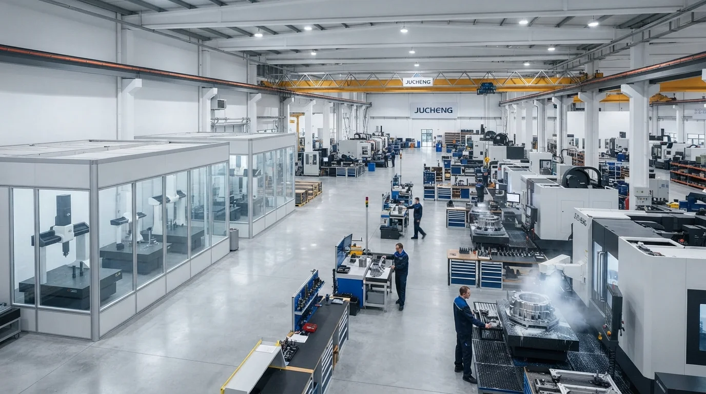
Achieving uncompromising flight precision requires an experienced contract manufacturing partner with certified metrology infrastructure and climate-controlled toolrooms. JUCHENG supports aerospace innovators by delivering comprehensive 24-hour free DFM reviews that analyze GD&T datums, toolpath clearances, and machine kinematics prior to cutting metal billet. Founded in Shenzhen in 2012 with an 8,000-square-meter facility in Dongguan, our factory houses 150+ advanced machines, including 25+ high-performance 5-axis Haas and Mazak milling centers alongside dedicated metrology labs [9.10].
Backed by ISO 9001, ISO 14001, ISO 13485, and IATF 16949 certifications, our engineering teams ensure that maintaining strict aerospace machining tolerances achieves sub-micron repeatability, complete AS9102 First Article Inspection (FAI) reporting, and absolute batch consistency.
Ready to Verify Your Flight Components with Sub-Micron Precision?
Upload your 3D models today to receive instant feedback, competitive pricing, and professional DFM analysis from our seasoned engineering experts. Let JUCHENG bring your complex designs to life with unmatched speed and reliability!

