


Read the geometry before choosing the machine
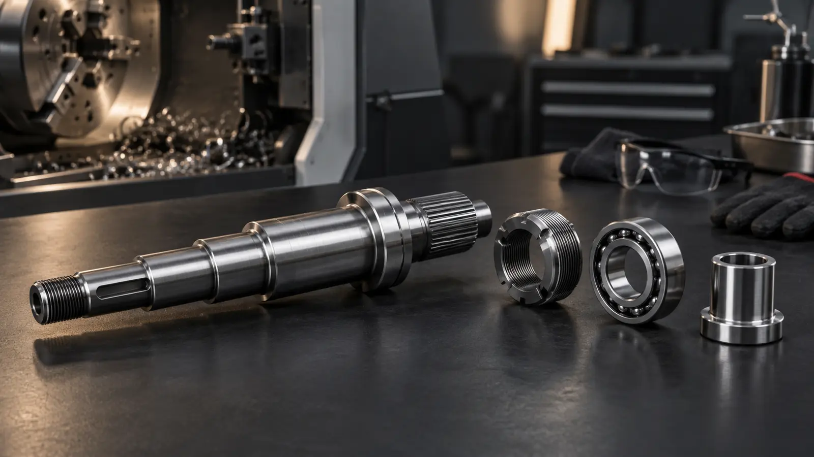
A turned part starts with rotational symmetry, but it does not have to remain completely cylindrical. Cross-holes, flats, slots, wrench features, and off-center details may require live tooling or a follow-up milling operation. The first review should separate the features that can be generated in one turning setup from those that need another orientation.
That distinction affects accuracy and cost. Every additional setup creates another opportunity for datum transfer, clamping marks, and accumulated error. A design with several coaxial diameters is usually efficient on a turning center, while a primarily prismatic bracket is usually better suited to milling.
For early vehicle programs, automotive rapid prototyping can use turned parts to test a real interface before the final production route is fixed. This is especially helpful when the test concerns assembly, rotation, sealing, or contact pressure rather than appearance alone.
Parts that benefit from turning
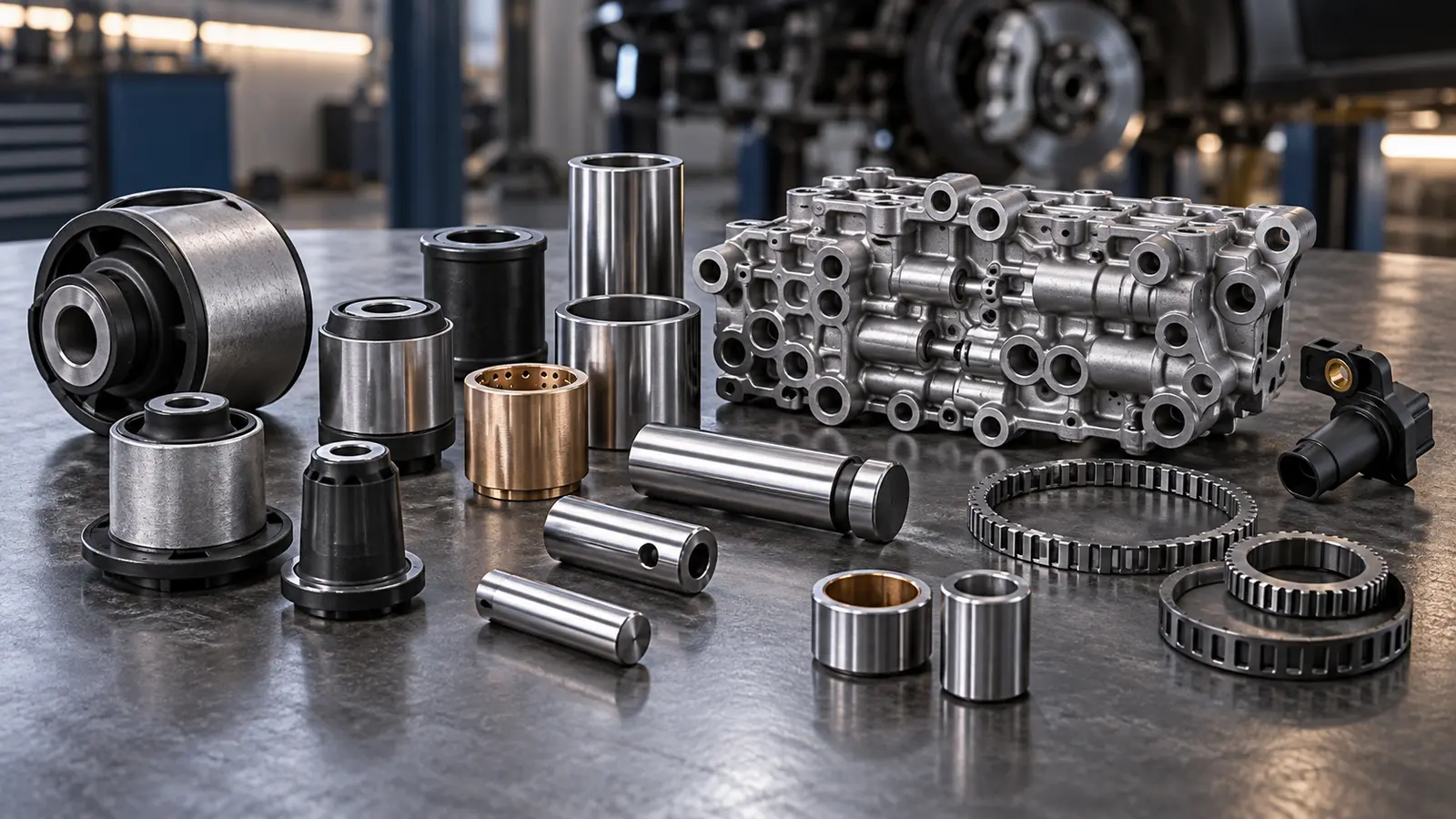
Automotive CNC turning supports more than engine hardware. It can also produce prototype and low-volume parts used in electric drivetrains, thermal systems, sensors, fixtures, and vehicle interiors.
| Part family | Useful turned features | Design question |
|---|---|---|
| Shafts and pins | Diameters, shoulders, grooves, threads | How will the part locate and resist rotation? |
| Bushings and spacers | Concentric bores and controlled lengths | What clearance or press fit is required? |
| Rotary adapters | Threads, sealing faces, wrench flats | Does the interface need repeated assembly? |
| Sensor sleeves | Thin walls, bores, steps, and retaining features | Will wall thickness survive machining and service? |
| Prototype tooling components | Locating diameters and replaceable wear surfaces | How many cycles and revisions are expected? |
The phrase “automotive part” does not determine the manufacturing process by itself. A small aluminum sleeve may be turned directly from bar stock, while a larger housing may need milling, casting, or sheet metal fabrication before critical bores are machined.
Features that control performance
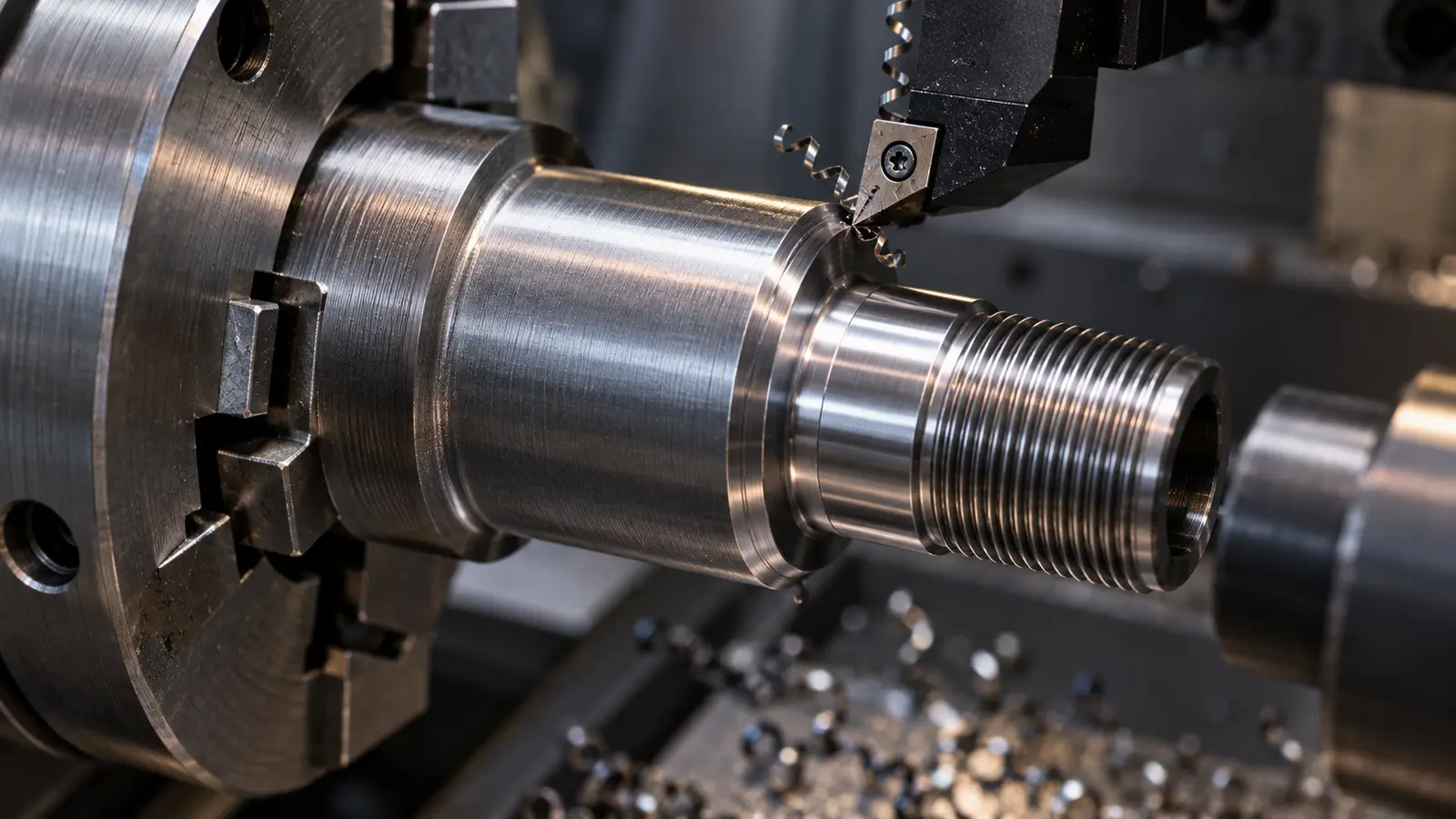
Diameter is only one part of a turning specification. Engineers should also review circularity, cylindricity, concentricity, runout, surface roughness, thread quality, and the relationship between a functional feature and its datum.
For example, a bearing seat may meet its diameter tolerance and still perform poorly if its axis is not aligned with the neighboring seat. A seal may leak even when the nominal bore is correct if the surface has tool marks running in an unfavorable direction. These are interface problems, not simply size problems.
- Identify the axis: define the centerline that governs the functional features.
- Separate fits from reference surfaces: do not apply the same tolerance logic to every diameter.
- Control the end condition: specify chamfers, burr limits, and face-to-axis relationships.
- State the thread requirement: include thread standard, class, depth, and inspection method.
- Define the finish: distinguish as-machined surfaces from surfaces requiring treatment.
These decisions help the supplier choose tooling, workholding, cutting conditions, and inspection methods before the first part is made.
Material and chip behavior
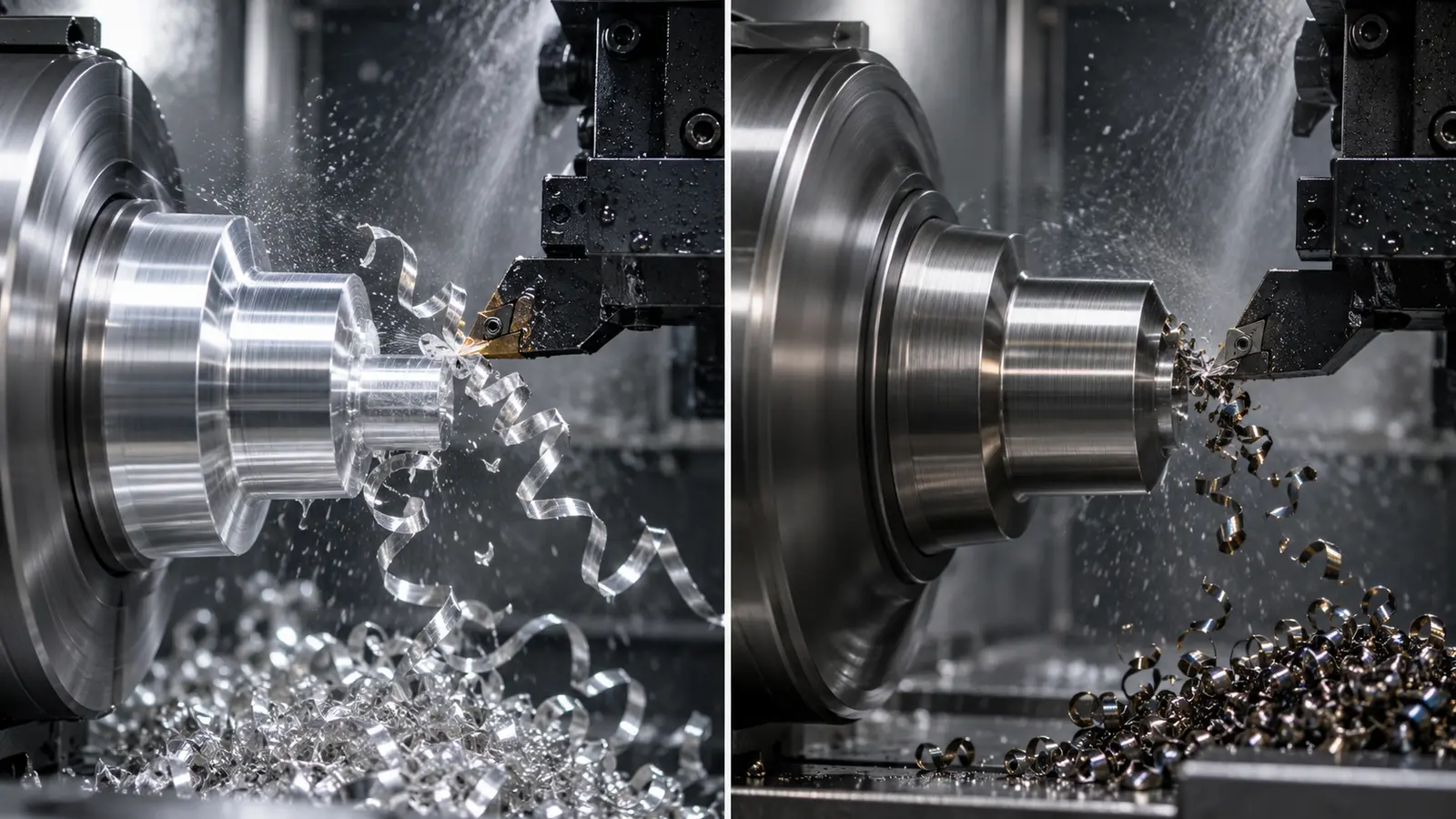
Aluminum is often selected for lightweight prototype hardware and housings because it machines efficiently and can accept finishes such as anodizing. Stainless steel may be selected for corrosion resistance or a more durable interface. Brass and copper can suit electrical, thermal, or low-friction requirements, while engineering plastics may be appropriate for insulating or low-load sleeves.
Material choice changes the turning strategy. Long stringy chips, work hardening, heat generation, burr formation, and deflection all influence tool selection and feeds. A material substitution should therefore be reviewed against the test purpose rather than accepted only because its nominal strength looks similar.
The main CNC machining service can be evaluated alongside the drawing, material callout, and quantity. This gives the manufacturer a basis for deciding whether bar turning, mill-turning, or a combined machining route is more suitable.
Inspection begins with the datum scheme
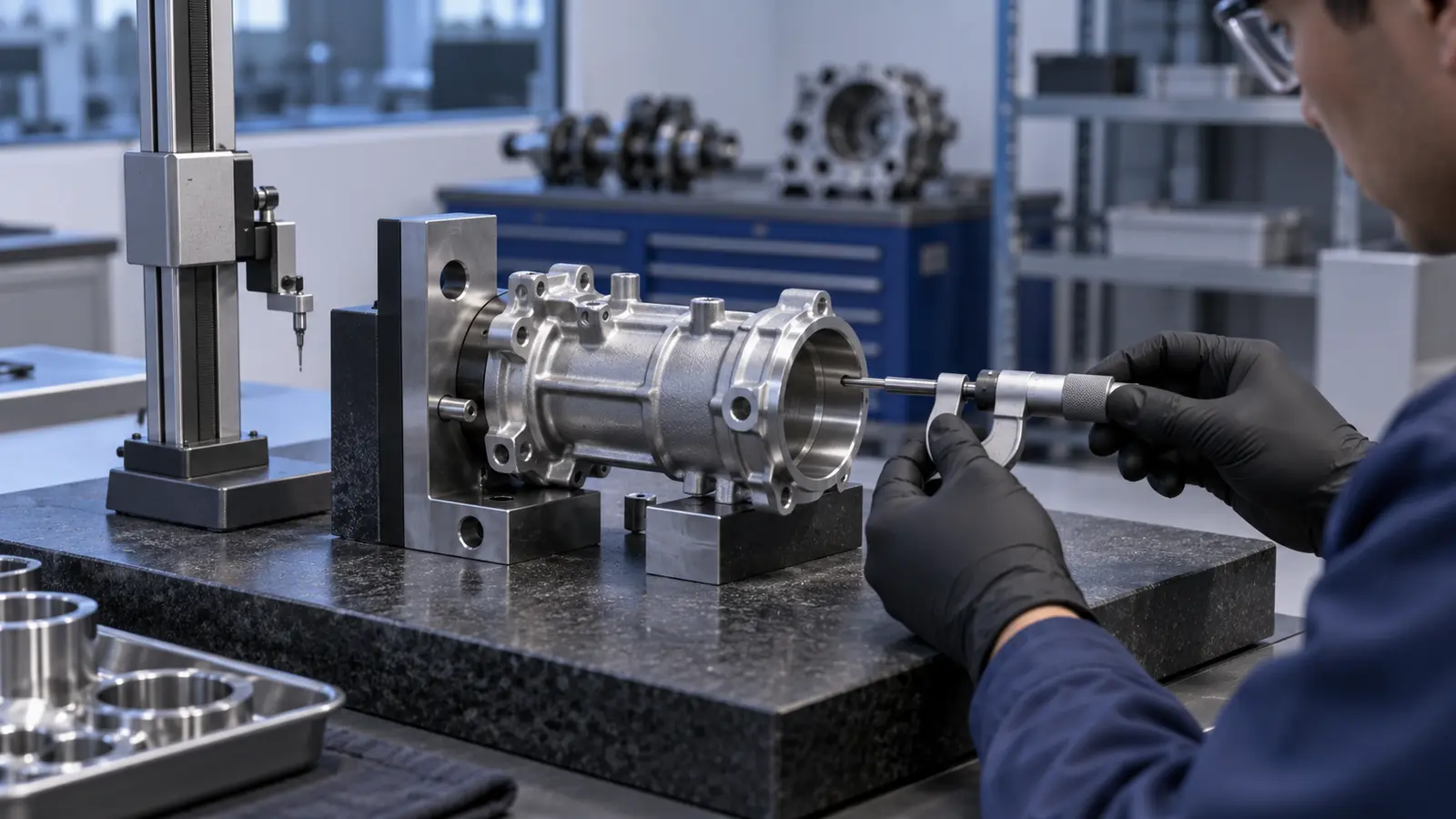
Inspection should answer whether the part will work in its assembly, not simply whether a list of dimensions was measured. A practical plan starts with the functional axis, the mating faces, and the features that control rotation, retention, sealing, or electrical contact.
Common tools may include micrometers, bore gauges, thread gauges, optical equipment, or a coordinate measuring machine. The correct instrument depends on feature size, tolerance, geometry, and the level of evidence required by the vehicle program.
A first-article report becomes more useful when it links each critical feature to its drawing requirement and measurement method. If a part is intended for a validation build, the report should also identify material, finish, quantity, and any deviations agreed during design review.
Where turning meets milling and finishing
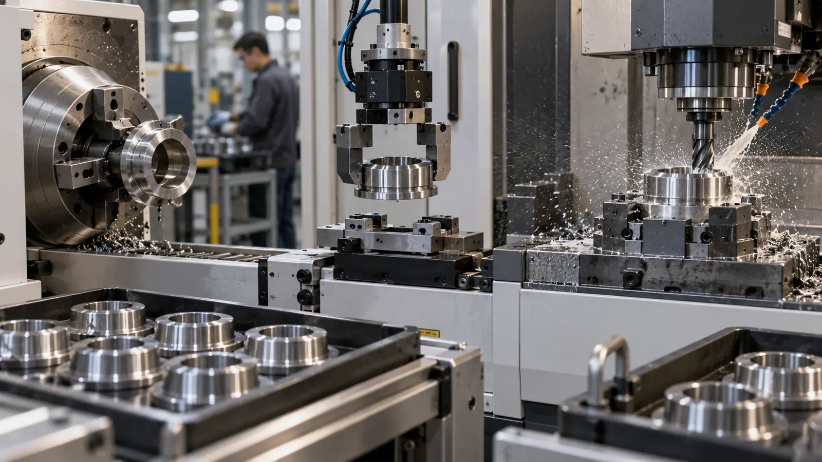
Many real automotive components need more than turning. A turned blank may receive milled flats, cross-holes, keyways, or bolt patterns. A mill-turning sequence can reduce handling when the machine and geometry allow it, while a separate milling operation may provide better access for a complex feature.
Turning can also be combined with casting. A cast housing may provide the bulk shape, then turning can finish a bore, face, or concentric seat. This route is useful when the design has moved toward production geometry but still needs accurate interfaces.
Finishing is part of the engineering chain. Surface finishing services may improve corrosion resistance, wear behavior, appearance, or handling, but coating thickness and masking can alter fits. The drawing should identify surfaces that must remain untreated or be re-machined after finishing.
How to prepare the RFQ
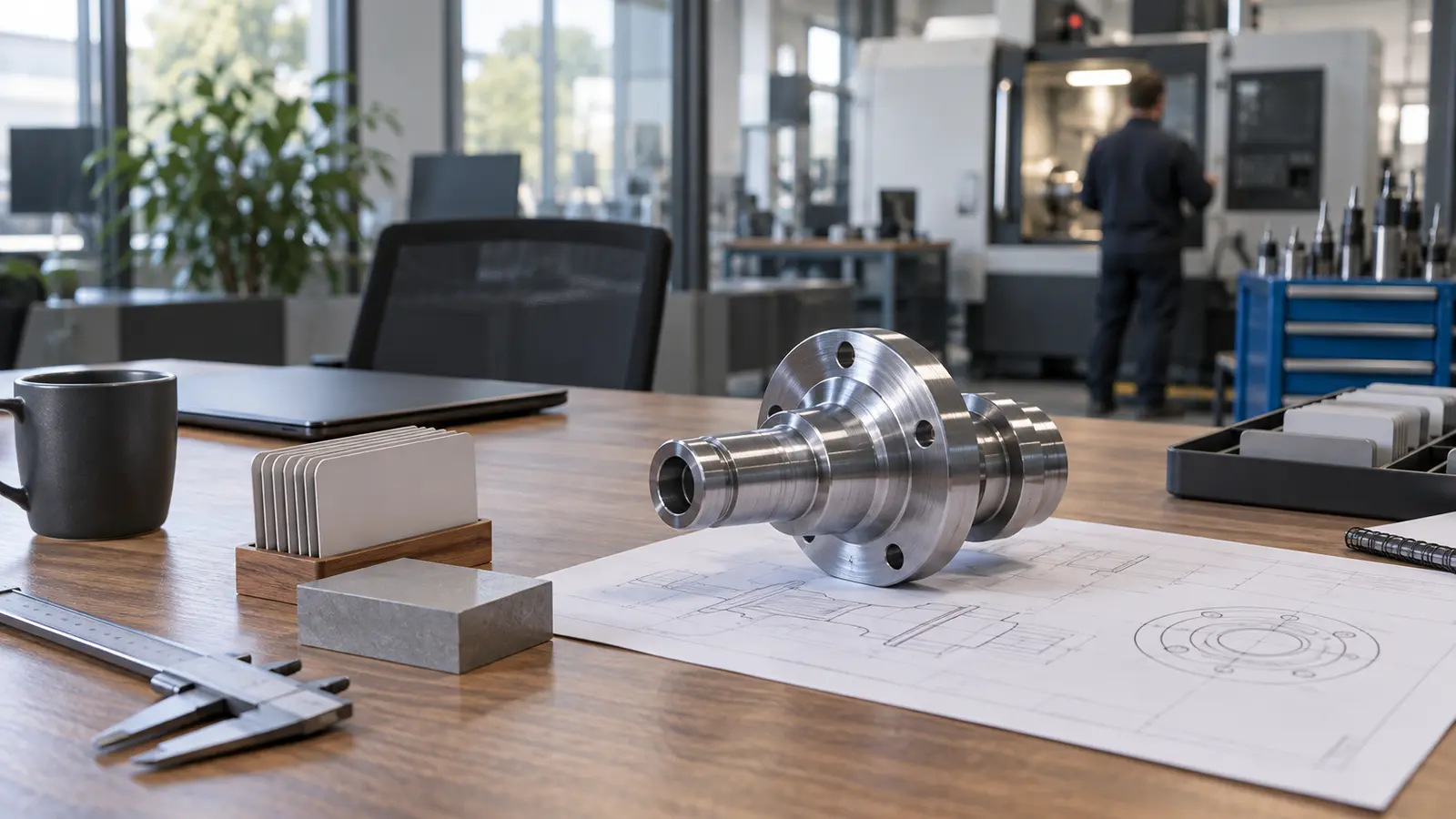
A turning quotation should include more than a STEP file. Send the 2D drawing, material, quantity, thread details, surface finish, critical tolerances, inspection requirements, and the intended assembly or test use.
| Input | Why it matters |
|---|---|
| Latest CAD and drawing | Prevents mismatches between model geometry and controlled dimensions |
| Quantity by stage | Separates prototype economics from repeat low-volume production |
| Material and treatment | Controls cutting behavior, corrosion, appearance, and final dimensions |
| Critical interface notes | Focuses inspection on the features that determine assembly |
| Report expectation | Aligns measurement scope before production begins |
Clear inputs also let a supplier compare turning with CNC milling, injection molding, die casting, or additive manufacturing without forcing one process onto every part.
Frequently Asked Questions
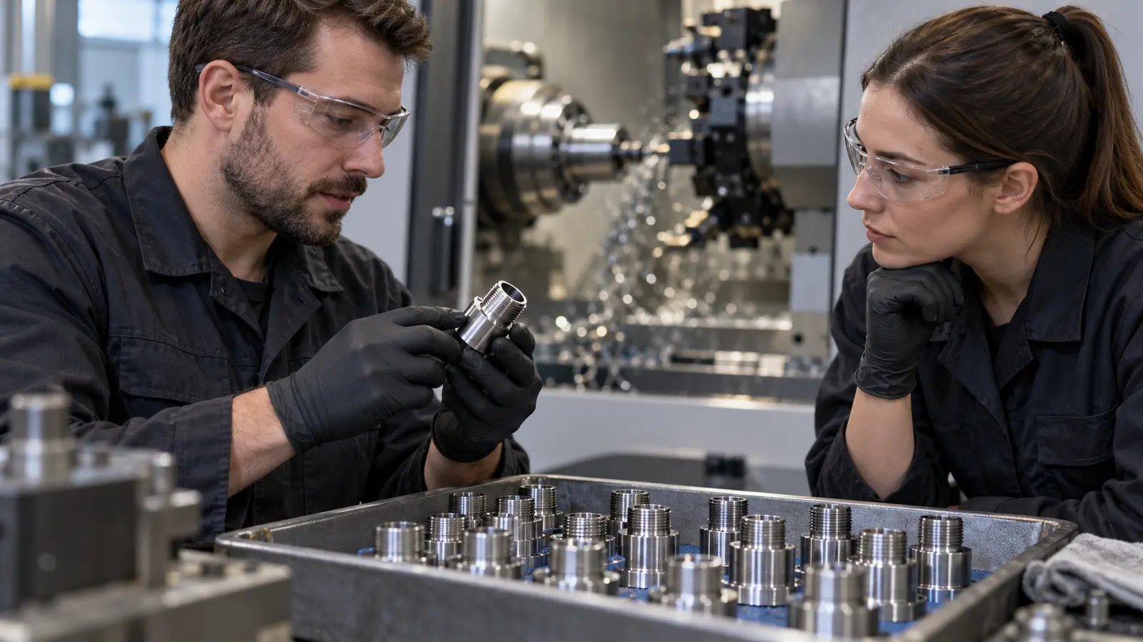
What automotive parts are made with CNC turning?
Common examples include shafts, pins, bushings, spacers, sleeves, threaded adapters, rotary connectors, and cylindrical housings. Parts with coaxial diameters or controlled bores are usually strong candidates.
What is the difference between automotive CNC turning and milling?
Turning rotates the workpiece to create round features around a centerline. Milling rotates cutting tools against a stationary or positioned workpiece and is better for flats, pockets, holes, and complex prismatic geometry. Many automotive parts combine both processes.
Can CNC turning make low-volume automotive components?
Yes. Turning is useful for prototypes, validation builds, service parts, and low-volume batches because it does not require dedicated molding or stamping tooling for each design revision.
Which materials can be used for turned automotive parts?
Depending on the design and test, turned parts may use aluminum, stainless steel, alloy steel, brass, copper, or engineering plastics. The material should be selected according to load, wear, corrosion, thermal, electrical, and validation requirements.
How should turned parts be inspected?
Inspection should focus on diameters, bores, runout, concentricity, lengths, threads, surface condition, and the features that control assembly. The drawing and test plan should determine the measuring tools and report scope.
Turn the part around the function
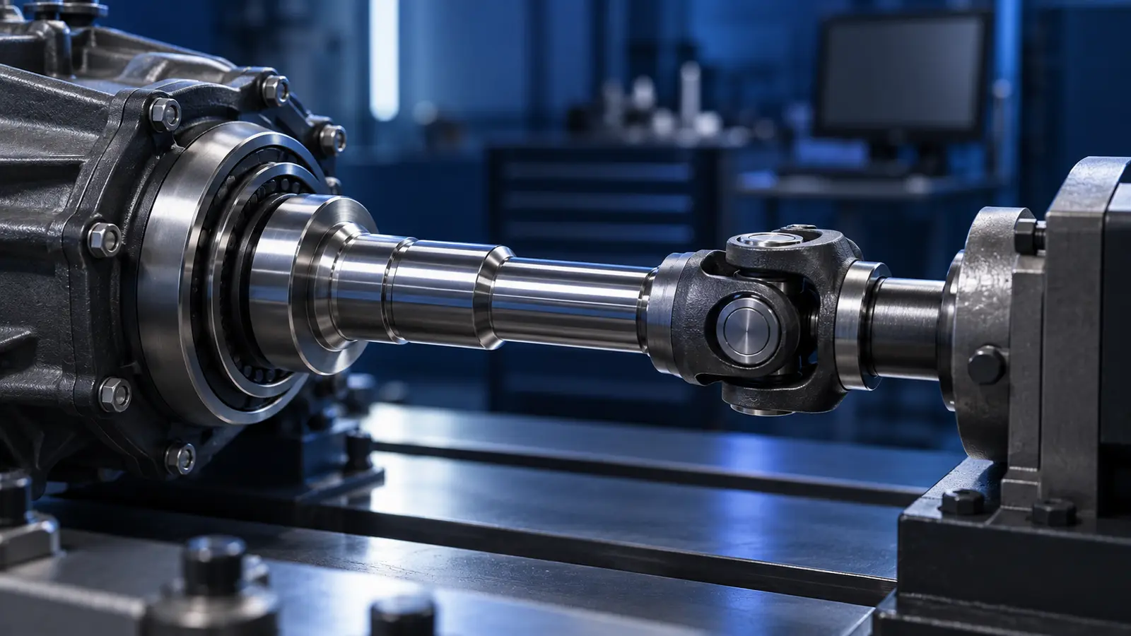
The strongest automotive CNC turning projects begin with the part’s functional axis and the next engineering decision. Once the team knows which surfaces rotate, locate, seal, retain, or carry load, it becomes easier to select the material, tolerance, tooling sequence, finish, and inspection plan. That logic produces a part that is useful in the vehicle program, not merely a round object made from a bar.
Jucheng Precision can review turned automotive components together with milled, molded, cast, printed, fabricated, and finished parts when a program needs a coordinated manufacturing route. Provide the drawing, quantity, and test objective for a practical process recommendation.

