


What the machining plan must protect
An oil pump housing is not simply a cover with a cavity. It locates the pumping elements, directs oil between ports, seals against a mating plate or cover, and carries fasteners that hold the assembly together. In a gerotor design, the rotor pocket and its relationship to the shaft or bearing features govern how the internal parts sit. In a gear pump, the relevant pockets and bores must likewise relate to one another and to the flow path. The drawing, not a generic pump description, determines which dimensions are critical.
That makes automotive oil pump housing machining a datum and process-sequence problem. A good plan starts by identifying the rotor or gear locating geometry, the mating sealing face, the inlet and outlet passages, and the mounting interfaces. It then selects a casting or billet route, chooses stable workholding, and defines how the features will be inspected after each operation. Starting with the outside contour can waste time while leaving the functional relationships unresolved.
Map each machined feature to its function
Before programming a toolpath, create a feature map. The same feature can have different significance across designs: a rotor cavity may be central to axial clearance, a bearing bore may set the shaft axis, and a cover face may close a pressure path. The feature map should connect the drawing characteristic to the assembly function and the inspection method. If the function is unknown or not fully defined, record the question rather than silently assigning a tolerance.
| Feature group | Relationship to review | Manufacturing question |
|---|---|---|
| Rotor or gear pocket | Position and depth relative to shaft/bearing axis and sealing plane | Can roughing and finishing preserve the specified geometry without part movement? |
| Shaft or bearing support | Coaxiality, location, and fit with the mating component | Is the bore reachable and measurable from the selected datum? |
| Cover or gasket face | Flatness and relation to ports and pocket depth | Does the finishing sequence avoid distortion or raised burrs? |
| Inlet/outlet passages | Connection to the internal cavity and external ports | How will intersecting-hole burrs and chip retention be controlled? |
This review often exposes missing drawing information. For example, a bore size may be specified but its axis relationship to the pocket is not clear; a sealing surface may have a finish note without a defined datum; or a port may be dimensioned at its entrance but not through the intersecting passage. Such questions should be resolved through the approved drawing or engineering clarification. A supplier should not invent functional requirements to make a quote look complete.
Choose casting or machining from the development stage
A machined billet can be useful when the objective is to test fit, revise a pocket, confirm the mounting envelope, or get a small number of parts before production tooling is justified. It also allows design changes without revising a casting tool. Its limits matter: it may not represent cast structure, local wall thickness, porosity, or residual stress. A prototype made from billet should therefore be labeled with the process route and used only for conclusions it can support.
For repeat demand, a cast near-net blank followed by CNC machining may reduce material removal and cycle time, depending on the housing geometry, alloy, and quantity. The casting drawing must show the intended finished geometry, machining allowances, draft, parting line, and any critical non-machined surfaces. Machining allowance should be adequate to clean up the interfaces while avoiding large stock variation that makes the setup unstable. The route can include casting, heat treatment where specified, shot blasting or other surface preparation, machining, deburring, cleaning, and inspection.
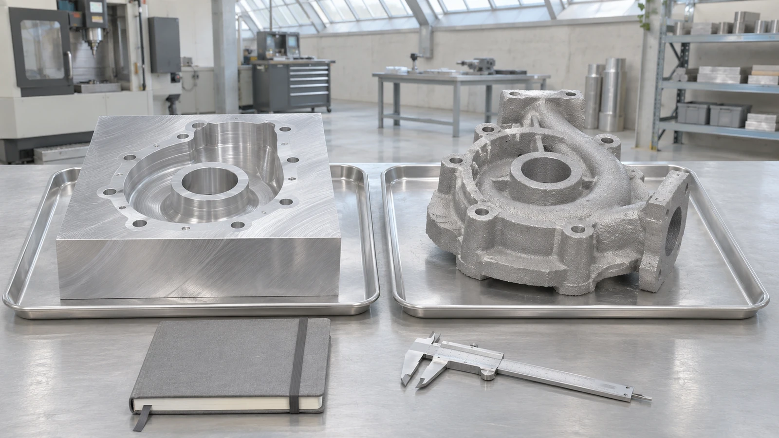
A quote should compare the complete route rather than only the machining cycle. Include tool or fixture cost, casting yield assumptions if known, inspection effort, finishing, sample quantities, and the cost of design revisions. A die casting route may suit a design and volume that support tooling, while a CNC machining route can serve prototypes or features that need direct machining control. The chosen material and condition should remain tied to the project specification; the aluminum machining resource is a starting point for process discussion, not a substitute for an approved grade.
Sequence operations around the pump datum
A typical planning logic begins by establishing stable reference surfaces, roughing the major pocket and bores, allowing the part to relax where the material and geometry warrant it, and then finishing the surfaces whose relationships control assembly. The actual order depends on the casting, part stiffness, workholding, and specification. If the rotor pocket and bearing bore share a functional relationship, the finishing plan should preserve that relationship and avoid unnecessary reclamping between them.
For castings, the first setup can be the hardest. As-cast surfaces may vary, so fixtures should locate the part without rocking and should resist cutting forces without distorting thin walls. A rough-machined datum can create a more repeatable second setup. If the design permits, machining key related faces in one setup reduces the number of transferred references. If not, define the locator scheme and the inspection checkpoint that confirms the transfer.
Tool selection should account for pocket corners, chip evacuation, reach, and tool deflection. Sharp internal corners may be impossible to produce with a standard cutter and can create unwanted stress concentrations or trapped debris. The drawing should state radii and edge breaks where they affect assembly or cleaning. Avoid adding a general “break all edges” instruction if it conflicts with a sealing land or a specified sharp edge.
Control intersecting passages and chip risk
Oil passages are functional channels, not incidental holes. Cross-drilling and intersecting features can leave burrs inside a path that is difficult to inspect visually. The engineering team should identify where passages intersect, how they will be deburred, and what evidence is required to confirm that chips or loose material are not retained. The acceptance method may be visual, borescope, flow, cleanliness, or another customer-defined check; do not imply a specific test unless the drawing or project plan calls for it.
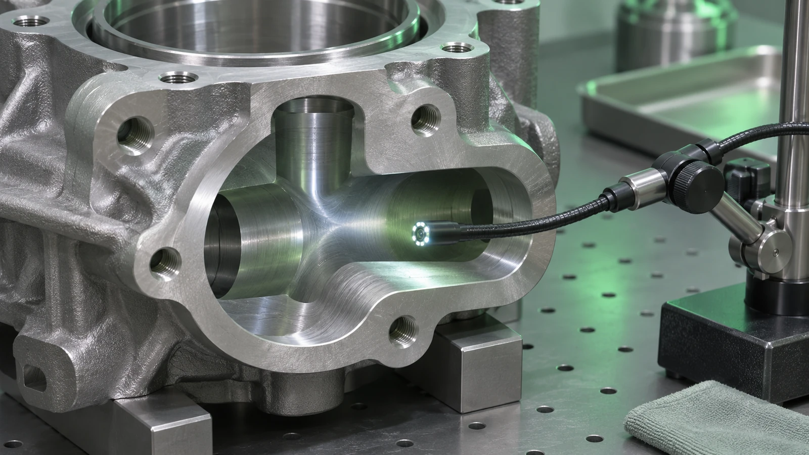
Deburring needs to remove harmful edges without changing a metering feature or enlarging a port beyond its definition. A process note should identify critical edges or passages, and the inspection plan should include a way to verify them. Cleaning is part of the manufacturing route because chips, abrasive residue, and process fluids can affect assembly and later testing. Define the cleanliness level or packaging expectation if it is part of the customer requirement.
Surface treatment, if specified, can change dimensions and friction at interfaces. Masking a bore or face may be appropriate, but the drawing and supplier should agree on the treated boundary. Confirm whether dimensions are evaluated before or after coating. The same logic applies to heat treatment and stress relief: specify the condition and verify the material documentation rather than treating them as unrecorded shop choices.
Verify a housing as part of the pump assembly
Dimensional inspection should reflect the feature map. Measure the bore or pocket dimensions, axis location, face geometry, bolt pattern, threads, and ports that are called out as critical. Use suitable gauges or coordinate measurement for each characteristic. A single measurement cannot establish the full geometric relationship. If an assembly fixture is used, document which mating interfaces it represents and what it does not prove.
A functional prototype review may check rotor freedom, cover seating, shaft alignment, seal installation, or port communication. These observations are useful when they are tied to a known part revision and assembly condition. They are not a substitute for a specified endurance, pressure, or performance validation. Procurement should request the reports required by the project instead of assuming a generic “tested” statement covers every characteristic.
Give the supplier a usable drawing package
Send the current drawing and 3D model, material designation and temper, annual or prototype quantities, surface treatment, and inspection/documentation needs. Clearly identify the pocket and bore datum scheme, sealing surfaces, passage intersections, and any characteristics that require a report. If the design is still evolving, mark the open questions and tell the supplier whether the sample is for visual review, assembly fit, or functional testing.
Ask for a process proposal that identifies the blank type, setup sequence, fixturing assumptions, finishing route, and inspection access. The supplier can then flag thin walls, unstable clamping surfaces, or passage features that need a special deburring plan. Clear questions at quotation stage reduce the risk of receiving a sample that matches the outside envelope but cannot answer the engineering question.
FAQ
Which feature is most important in oil pump housing machining?
There is no universal single feature. The rotor or gear location, bearing support, sealing plane, and passages each matter according to the pump design and drawing. Identify the relationships that control assembly and function before assigning inspection priority.
Should an oil pump housing be cast or machined from billet?
The answer depends on quantity, geometry, schedule, and what the prototype must prove. Billet machining avoids casting tooling for low quantities; casting with finish machining may suit a repeat route where tooling and near-net geometry are justified.
How can internal passage burrs be managed?
Identify intersections on the drawing, select an accessible deburring method, clean the part, and define an inspection or cleanliness check suitable for the requirement. A generic external edge-break note does not control hidden passage burrs.
What information should accompany a prototype order?
Provide the revision-controlled drawing and model, material, quantity, critical interfaces, finish, and the specific fit or functional questions the prototype must answer. State which dimensions, tests, and records are required.
The rotor pocket is only one part of the job. A robust housing route connects that geometry to the supporting bore, sealing plane, oil passages, and assembly datums, then uses inspection evidence that matches the design intent. That is how a machining plan becomes a useful engineering and sourcing decision rather than a list of operations.