


A transmission case can pass a visual check and still create a difficult assembly: bearing bores do not share the intended axis, a cover face rocks, or a seal land shifts after the part is clamped. These problems usually begin earlier than the final cut. They begin when the drawing does not identify which faces and axes control the assembly, or when a machining plan treats each feature as an isolated dimension.
For automotive transmission case machining, the useful question is not simply whether a machine can reach every surface. It is whether the part can be located, machined, and inspected from a stable datum scheme that preserves the relationships the transmission depends on. That makes the case a natural companion to a transmission valve body machining review: one concerns the structural enclosure and its interfaces, while the other concerns the hydraulic control component inside it.
What the case must locate
A transmission case is a structural reference for several assemblies. Depending on the design, it may locate shafts, bearings, covers, seals, hydraulic components, mounting brackets, and external interfaces. The exact feature set varies by transmission architecture, so a supplier should work from the released drawing and model rather than assume that every case uses the same datum scheme.
Start by separating functional interfaces from convenient-to-machine surfaces. A mounting pad may establish how the assembly sits in the vehicle. Bearing bores may control shaft location. A cover flange may provide a sealing plane. Threaded holes may retain a cover but may not define its position. If all of these are treated as equally important, inspection becomes unfocused and the setup plan can optimize the wrong face.
A practical drawing review asks what must remain aligned after the part is removed from the fixture. That question matters because a feature can measure correctly while clamped and move when residual stress, thin walls, or uneven material removal allow the casting or billet to relax. Record the critical relationships—such as bore-to-bore position, bore axis to mounting plane, and sealing face to the mating component—before deciding how many setups the part needs.
Build a datum plan before choosing setups
Datums should represent how the case is located in its assembly or in a defined inspection fixture. They should not be selected only because a surface is large and easy to touch. A stable primary plane can establish orientation; a secondary feature can control translation or rotation; a tertiary feature can complete location. The drawing’s geometric dimensioning and tolerancing scheme determines the actual datum precedence.
For a multi-bore housing, preserve the relationship between the bore group and the selected datums through the machining route. If the part is flipped and re-zeroed from unrelated surfaces, each setup can add a new source of alignment error. A common fixture datum, repeatable locating features, or a planned reference transfer can reduce that risk, but the right choice depends on the geometry, stock condition, quantity, and inspection method.
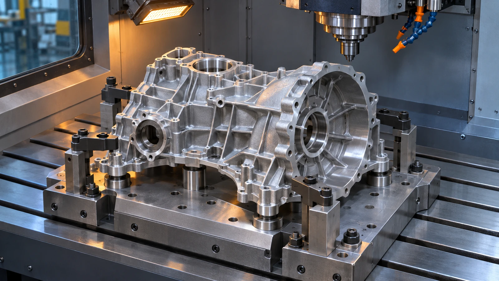
Also separate location from clamping. Locators establish where the part sits; clamps hold it there. Clamping directly across a thin wall or a large unsupported span can distort the case temporarily. If the bore is finished under that load, the released part may not retain the measured size or position. The drawing review should identify thin sections, ribs, open windows, and asymmetric stock so the fixture can support the part without masking the finished geometry.
Sequence features around distortion and access
Machining order is a design decision because it affects both access and stability. A typical planning discussion begins with the surfaces that establish the datum structure, then addresses major bores and mating faces, followed by secondary holes, threads, and deburring. That is not a universal fixed sequence: tool reach, casting stock, heat treatment, material condition, and feature relationships can change the order.
Roughing and finishing may need different strategies. Rough removal creates access and removes most of the stock; a later finish pass can restore the final geometry after the part has stabilized. Where a feature is sensitive to clamping or material release, leave a controlled allowance for the finishing operation rather than assuming the first cut will be final. Any allowance and sequence must be agreed against the drawing and the part’s material condition.
Internal passages and intersecting holes deserve their own plan. Tool access may be restricted, and cross-drilled intersections can leave burrs where a visual check cannot reach. Specify how the passage will be cleaned and how the relevant features will be inspected. A drawing that says “deburr all edges” may not fully define the required condition inside a long or angled passage; identify the critical flow or sealing zones and acceptance method.
For adjacent transmission components, keep the content boundary clear. A shift fork machining discussion concerns a moving engagement component. The case article should stay centered on enclosure geometry, bearing support, mounting, sealing, and how those features are controlled during machining and inspection.
Choose the route from the blank and quantity
The starting blank changes the planning problem. A casting may arrive with draft, parting-line stock, local variation, and a material history that the machining plan must accommodate. A billet route may offer a different path for a prototype or low-volume part, but it can change material use, cycle planning, and the relationship between the machined geometry and the intended production route. The drawing, alloy specification, available stock, and required quantity should drive that comparison.
Do not treat “aluminum case” as a complete material specification. The exact alloy, temper or casting condition, heat-treatment status, and any required surface or corrosion treatment matter. Those details can affect machinability and dimensional stability. If the specification names a particular material condition, a proposed substitution needs engineering approval rather than an informal assumption that a similar alloy will behave the same way.
Surface treatment can also alter dimensions or change the way a mating face is finished. Decide which surfaces are masked, machined after treatment, or included in the final inspection. If a sealing face, bearing fit, or locating interface has a finish requirement, state whether it applies before or after the specified treatment. This avoids a late disagreement about whether the measurement describes the raw machined surface or the completed part.
Inspect relationships, not just diameters
A bore report should identify more than a nominal diameter. Depending on the drawing, the inspection plan may need size, form, position, axis orientation, and relationship to a datum. A bore that is individually within size can still be misplaced relative to another bore or a mounting plane. Likewise, a face can meet flatness while its position relative to the shaft axis is incorrect.
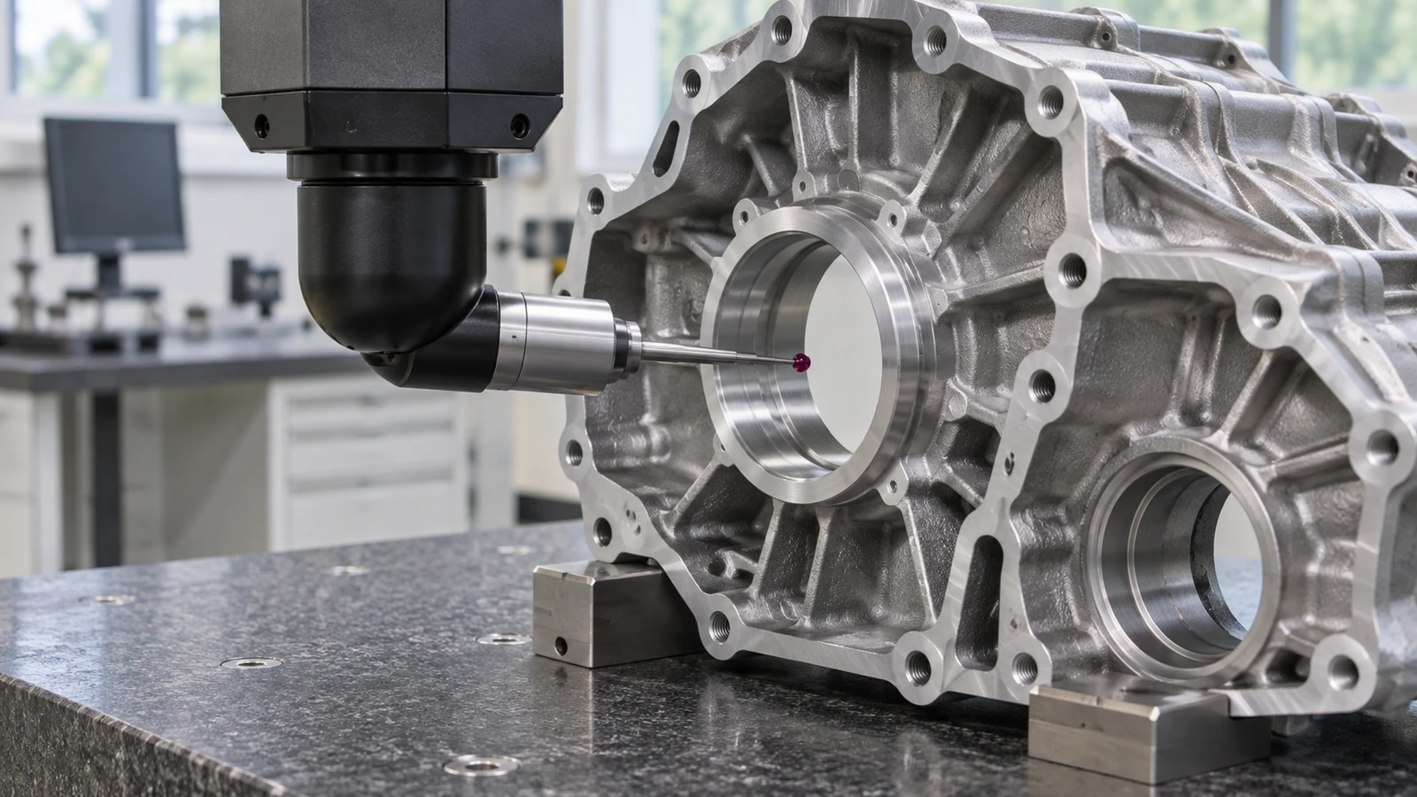
Match the method to the characteristic. A bore gauge may check size at selected depths; it does not by itself establish the bore’s position in a datum reference frame. A coordinate measuring machine may evaluate relationships, but the setup, probe access, alignment routine, and drawing requirements still matter. For first articles, agree on the datum simulation and report format before inspection begins so supplier and customer read the same feature-control scheme.
Record the part identity, drawing revision, material condition, operation state, and inspection setup with the results. This helps separate a machining issue from a revision mismatch or a measurement setup change. For prototypes, the goal is not to produce a large report by default; it is to document the characteristics that answer the design question and support the next decision.
What to include in a case-machining RFQ
A useful request for quote includes the current 2D drawing, the 3D model, revision identifiers, material and condition, expected quantity, surface-treatment requirements, and the critical-to-function characteristics. Mark features that require a formal inspection report and state whether parts are prototypes, bridge quantities, or intended to represent a later production process. If the production blank is not yet fixed, ask for the route assumptions to be stated in the quotation.
Include the mating context for features whose purpose is not obvious from the part view: which cover seals to the flange, which bore supports a shaft, or how the case locates in the larger assembly. This information can prevent a supplier from optimizing a noncritical cosmetic face while missing a functional relationship. If a tolerance appears unusually tight or conflicts with the available datum scheme, raise the question before cutting metal.
For a prototype or low-volume program, a supplier should be able to explain the proposed setup sequence, inspection approach, and any unresolved assumptions. A drawing-based review of automotive prototype machining requirements can help connect the case geometry to the broader development schedule without treating the prototype as proof of a production process.
FAQ
Is transmission case machining the same as transmission housing machining?
The phrases are often used for closely related enclosure parts. The drawing and assembly function decide the scope. A case article should explain the particular structural, bearing, mounting, sealing, and inspection relationships rather than rely on a naming distinction alone.
Can a machined prototype prove the production casting will hold alignment?
Not automatically. A prototype made from a different blank or material condition can answer design and fit questions, but it may not reproduce casting variation, residual stress, or production-process behavior. State what the prototype is intended to validate.
Which features deserve inspection priority?
Prioritize the characteristics tied to assembly function and the drawing’s geometric controls: datum relationships, bearing or shaft-support features, sealing interfaces, mounting locations, and any passage or thread identified as critical. The released specification remains the acceptance authority.
What is the most common planning mistake?
Treating every feature as an independent cut. The case is a network of relationships, so the fixture, sequence, and inspection plan must preserve and verify those relationships after the part is released from the machine.