


A handle connects the user, mechanism, and working end
A surgical instrument handle is not merely a shaped grip. It can connect the operator’s hand to a jaw, driver, shaft, ratchet, trigger, or rotating mechanism. Its bores, pivots, slots, fastener seats, and grip surfaces influence how the instrument assembles and moves. The manufacturing plan should begin with those interfaces and the drawing, then decide which features are machined, molded, overmolded, or assembled.
Surgical instrument handle machining is a distinct topic from overmolding a robot handle. Some designs use a machined metal body; others combine a metal core with polymer grip features or molded components. The relevant search and sourcing question is how to make the handle body and maintain its mechanical interfaces, not how to select a clinical instrument or claim patient outcomes.
For broader medical-device prototyping context, see the medical device industry page. This article stays focused on the component-level decisions that affect drawing review, machining, finishing, and assembly fit.
Translate the handle mechanism into controlled features
Start with a functional breakdown. Which surfaces contact the hand? Which features connect to the shaft or working end? Where does a pivot, pin, screw, spring, or latch locate? Does the design include a rotating or articulating connection? These questions help separate cosmetic surfaces from features that control motion or assembly. A hole can be a simple clearance feature in one design and a critical pivot bore in another; the drawing should distinguish them.
| Feature family | Design intent to clarify | Manufacturing focus |
|---|---|---|
| Pivot or hinge bore | Axis, spacing, and relation to the mechanism | Datum strategy, bore quality, and post-finish dimension |
| Shaft or end-effector connection | How the handle transmits motion or force | Fit, thread, slot, key, or joining feature from the drawing |
| Grip contour | Hand contact, orientation, and texture limits | Tool access, texture process, and cleanable transitions |
| Fastener seat | Retention, access, and assembly direction | Counterbore, thread, edge break, and assembly clearance |
If the handle contains multiple moving components, identify the stack-up and the reference parts used to check it. A pivot bore can be in size yet create a binding mechanism if the center distance or axis relationship is wrong. For a prototype, specify whether the supplier should deliver a standalone body or an assembled sample with customer-provided components.
Choose a body geometry that can be held and finished
Ergonomic contours can require multi-axis access, special fixtures, or a different split of components. A deep channel may be easier to machine before a cover is assembled; a narrow internal corner may require a larger radius; an undercut may lead to a separate component or a forming/molding operation. The design review should identify where tool reach, fixture contact, and inspection access become limiting.
A handle body machined from billet can support early geometry studies and low quantities, particularly when the design is still changing. A molded polymer grip, insert-molded design, or multi-part assembly may suit a different geometry or volume. The prototype method should represent the feature being evaluated. A machined metal handle can confirm a pivot or shaft connection but cannot validate the feel or behavior of an unrepresented overmold.
Thin walls and asymmetric forms can move during machining or after release. Use a datum plan that locates on stable surfaces and avoids crushing or bending the part. If the handle is split into two halves, define the seam, fastener pattern, alignment features, and the inspection state—individual part or assembled condition.
Match machining and molding to the design
CNC machining is appropriate for many metal handle bodies, pivot features, bores, threads, and custom contours. Low-volume molding can support polymer grip components or a design that combines molded and machined parts. A hybrid route may include a machined insert, a molded shell, secondary finishing, and assembly. The choice depends on the approved material, quantity, geometry, and which prototype or production evidence is needed.
Compare total route cost rather than a single operation. Include material, fixtures, mold tooling if applicable, finishing, cleaning, inspection, and revision risk. The site’s CNC machining capability is relevant to metal body features, while low-volume injection molding can be considered for compatible polymer handle features. The correct route should be agreed from the drawing rather than inferred from a generic handle description.
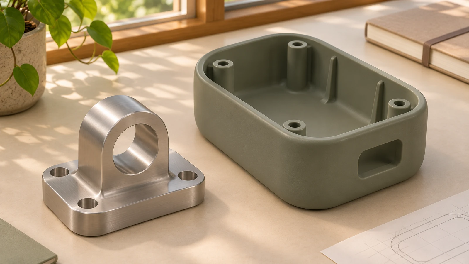
Treat grip texture and surface finish as separate needs
Grip texture is a functional and tactile design feature; it is not the same as a general cosmetic finish. Knurling, grooves, blasted texture, molded texture, or a coating can produce different surfaces and can affect cleanability, dimensions, and contact. The drawing should specify where texture is required, the intended pattern or reference, and the boundaries that must remain smooth or dimensionally controlled.
For pivot bores and sliding surfaces, surface requirements should be driven by the mating mechanism. For external surfaces, the finish may be selected for appearance, hand contact, or process compatibility. If passivation, electropolishing, anodizing, coating, or another treatment is specified, confirm which features are treated and how dimensions are verified afterwards. A finishing operation should not round an edge or close a clearance that the mechanism requires.
Material choice follows the approved application. Stainless steel, aluminum, titanium, PEEK, or other polymers may be specified in different handle designs. The stainless steel, titanium, and PEEK machining pages are starting points for material discussions, not substitutes for a controlled material designation.
Build inspection around pivots and interfaces
Inspect the characteristics that control assembly: pivot center distance, bore size and position, shaft interface, fastener features, seam alignment, grip profile where specified, and surface condition. Use a measurement method capable of observing the feature. A pin gauge can check a bore size, but it does not establish location or orientation relative to the handle axis.
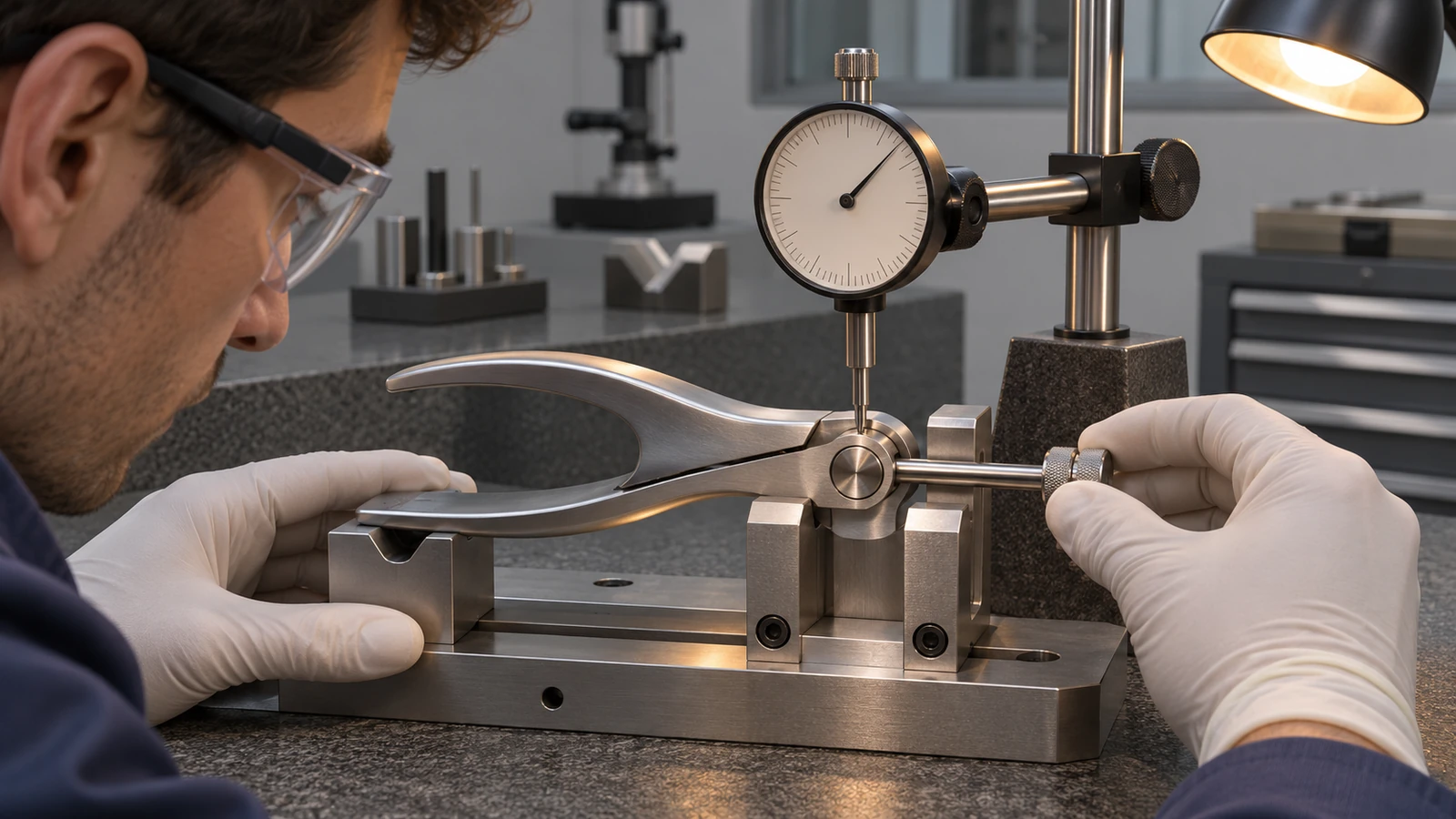
A functional assembly check can confirm that a pivot moves or a shaft connection engages under a defined setup. Document the components and condition used. Do not present a simple fit check as a sterilization validation, clinical assessment, or regulatory acceptance. Those evaluations belong to the device owner’s defined validation process.
When cleaning or passivation is required, specify the expected condition and packaging. Record material lot and drawing revision where required by the procurement documents. If the handle changes from machined metal to a hybrid design, revisit the inspection plan because assembly interfaces and material transitions change.
Prepare an effective supplier handoff
Provide the 2D drawing, 3D model, material and condition, quantity by phase, target finish, and documentation requirements. Identify the pivot axes, working-end connection, fastener seats, grip texture, and any interfaces that must be evaluated in an assembly. State whether the prototype is a metal body, polymer grip, overmolded component, or complete assembly.
Ask for a DFM review of tool access, datum selection, texture boundaries, cleaning access, and finishing sequence. If the design includes several materials, define their transition and joining method. The quote should also state which items are included in the sample and what inspection evidence will accompany it.
FAQ
Is machining alone enough for every surgical handle?
No. Some designs use machined metal bodies, while others combine machining with molding, overmolding, finishing, or assembly. The drawing and prototype objective determine the route.
What makes a handle pivot feature critical?
Its size, location, axis, and relation to adjoining features can control movement and assembly. The drawing should define those relationships and the inspection method.
Should grip texture be specified on the drawing?
Yes, when texture is required. Define its location and pattern or reference, and separate it from general surface finish so it can be manufactured and inspected consistently.
What can a handle prototype verify?
It can support the agreed fit, mechanism, and geometry checks for that sample. It does not by itself establish device-level validation or clinical performance.
A surgical handle works as a chain of interfaces: hand contact, mechanism, shaft, and working end. When those interfaces are drawn, machined, finished, and inspected as a connected system, the handle is easier to source and develop without treating every surface as a generic grip.