


A surgical retractor may look like a simple formed blade with a handle, yet its manufacturability depends on several interfaces working together: the blade profile, edge condition, neck transition, handle geometry, and any hinge, ratchet, or locking feature. Each detail can have a different manufacturing route. Treating the retractor as one undifferentiated metal shape makes it easy to miss how forming springback, machining datums, joining sequence, and finishing affect the final assembly.
This article discusses custom surgical retractor machining and fabrication from a supplier-planning perspective. It is not clinical guidance and does not define a suitable instrument design. The device manufacturer controls the approved drawing, material specification, validation, and acceptance requirements. A manufacturing partner can support prototype builds, evaluate process access, and propose inspection methods against those requirements.
For the broader context, see the medical device manufacturing page. The focus here is how the part’s shape and assembly architecture determine which operations belong in the route and where dimensional control matters most.
- Separate the blade, neck, handle, and locking features
- Control blade contour and edge condition
- Choose between forming, machining, and a combined route
- Plan the handle connection and assembly datums
- Make finishing and cleaning part of the process plan
- Inspect functional relationships, not just overall size
- What a retractor manufacturing RFQ should include
- FAQ
Separate the blade, neck, handle, and locking features
Start by identifying the architecture shown on the drawing. A retractor may be a one-piece component, a formed blade joined to a handle, or an assembly that includes a hinge or ratchet. Do not assume all designs are manufactured alike. Build a feature list for the blade width and contour, thickness, working angle, neck transition, handle profile, attachment interface, and any teeth or engagement surfaces.
Next, identify the datums used to relate these features. If the blade angle is controlled relative to a handle centerline, the production and inspection setups need a repeatable way to establish both. A drawing that controls only individual dimensions may still leave ambiguity about the assembly relationship. Resolve that ambiguity before quoting or programming rather than selecting a convenient reference and treating it as design intent.
| Part region | Manufacturing risk | Drawing or inspection question |
|---|---|---|
| Blade contour | Profile distortion or inconsistent edge radius | Which contour, thickness, and edge characteristics are controlled? |
| Neck transition | Local stress concentration or inaccessible finishing | Are radius, angle, and surface condition defined? |
| Handle connection | Misalignment after joining or inconsistent fit | What establishes orientation and engagement? |
| Locking feature | Tooth pitch, clearance, or hinge motion variation | Which dimensions and functional checks are acceptance criteria? |
Control blade contour and edge condition
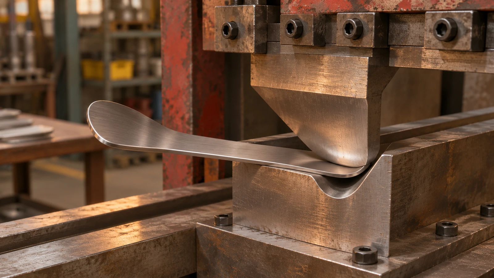
Blade geometry often combines a thin section with a curved or angled profile. The process must produce the defined shape without leaving an uncontrolled edge or distorting the part during clamping. For a formed blade, the flat pattern, bend sequence, tooling contact, and expected springback should be reviewed against the final profile. For a machined blade, workholding must support the thin section while keeping the cutting tool accessible to the contour and transition surfaces.
Edge terminology needs to be precise. A drawing may specify a radius, chamfer, edge break, or burr limit; each describes a different condition. If the edge requirement is absent, the supplier should raise a clarification rather than infer a value from a product photo or a similar part. A finishing operation should not soften a controlled contour or remove material beyond the defined profile.
The transition between blade and neck is another frequent inspection challenge. A small internal radius can be difficult to reach with a standard cutter, and a formed transition can change shape after release from the tool. Choose a measurement method that can see the controlled surface. A visual check can identify damage, but profile or thickness requirements may need optical measurement, a comparator, a CMM, or a customer-approved fixture.
Choose between forming, machining, and a combined route
Sheet metal forming can be efficient for suitable blade and handle geometries, particularly when thickness is consistent and the contour can be produced with accessible tooling. CNC machining may be appropriate for thicker sections, complex transitions, prototypes, or features that need to be related to common datums. Some designs benefit from a hybrid route: form the broad shape, then machine selected interfaces or locating features. The right choice depends on the controlled geometry, quantity, material, and inspection plan.
For a formed part, consider bend allowance, tool radius, grain direction where relevant to the material and forming operation, and springback. These are process-planning variables, not universal design values. The released drawing and material data govern. For a machined component, review cutter reach, clamping, burr access, and whether the thin areas can be supported without marking or distortion. The sheet metal fabrication service and CNC machining capabilities can support different portions of a custom route depending on the design.
Material selection should follow the customer’s specified grade and condition. Stainless steel is often selected for instrument components, while other alloys may be specified for a particular design. A material choice affects forming response, machinability, surface finishing, and joining considerations. The supplier should verify the exact designation and condition before quoting; generic labels are not sufficient for controlled procurement.
Plan the handle connection and assembly datums
If the blade and handle are separate parts, define their interface before selecting the joining process. The drawing should establish insertion depth, orientation, engagement length, and the relationship between the assembled blade plane and handle. A press fit, mechanical interlock, weld, braze, or other joining approach cannot be selected by name alone; the design authority must approve the method and its acceptance criteria.
Joining can move a thin blade or alter alignment. Create the datums and inspect critical features at the stage where they remain accessible. If final assembly obscures a joint, the plan may need pre-assembly measurements and a final orientation check. For hinged or ratcheting designs, the inspection plan should distinguish free movement, engagement, and dimensional characteristics; a single visual confirmation does not replace defined checks.
Prototype builds are useful for reviewing fixture access, assembly sequence, and inspection repeatability. Record the revision of each component and any approved deviation so fit observations do not become informal substitutes for drawing changes. If a prototype reveals that the connection is difficult to assemble or inspect, route that evidence back to the design review before production release.
Make finishing and cleaning part of the process plan
Surface finishing should be specified in measurable or visually unambiguous terms. A finish label may not define roughness, appearance, coverage, or the condition of edges and recesses. Identify which surfaces receive treatment, which surfaces must remain protected, and what inspection verifies the result. Where a finishing operation can change a dimension or edge, schedule verification after that operation.
Cleaning and packaging requirements should likewise be documented. Clarify handling, separation, protection from contact damage, and any required records. Do not infer sterilization, cleanliness class, or clinical readiness from the fact that a component has been machined or cleaned. Those requirements come from the product specification and the manufacturer’s validated processes.
When several suppliers perform forming, machining, joining, and finishing, agree on the handoff condition at each stage. Identify who owns part identification, revision traceability, inspection records, and nonconformance communication. Clear handoffs reduce the risk that an acceptable intermediate part becomes difficult to trace after downstream work.
Inspect functional relationships, not just overall size
A retractor can meet its overall length and still miss a critical blade angle, handle alignment, edge condition, or locking-feature relationship. Build inspection from the datum structure and risk-ranked characteristics on the drawing. Use calipers only for dimensions they can adequately verify; use profile measurement or fixtures when the specification requires a relationship that simple linear measurements cannot establish.
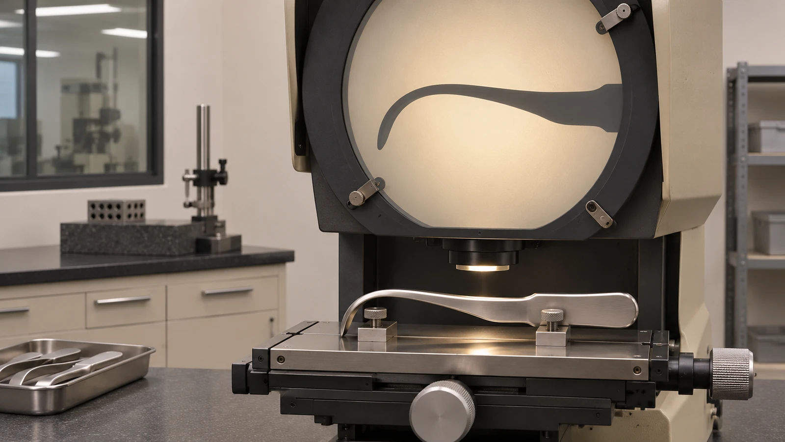
The control plan should state the sampling frequency, equipment, setup, acceptance criteria, and record format agreed with the customer. For a prototype, first-article evidence can document the measurement setup and identify features that need design clarification. If a functional assembly check is required, define the fixture, the condition being assessed, and how the result is recorded. Avoid making subjective “feels right” checks the only evidence for a controlled interface.
Where a special process is specified, identify its approved source and required documentation before the production route is released. Inspection after a special process should be chosen based on what that process may change. The supplier should report objective results and raise deviations through the customer’s agreed approval path.
What a retractor manufacturing RFQ should include
A complete RFQ package lets the supplier evaluate both the component and its route. Include a controlled drawing, 3D model when available, material and condition, quantity, finish, critical features, and inspection expectations. For multi-part designs, include assembly drawings and mating components or interface data. State whether the scope includes forming, CNC machining, joining, finishing, inspection reports, or only selected operations.
- Identify the exact material designation and condition, not just a generic family.
- Mark the blade profile, edge, handle orientation, hinge, and ratchet characteristics that control acceptance.
- Define forming or machining constraints, joining approvals, finish, cleaning, packaging, and traceability.
- Provide the drawing revision and a contact path for technical questions or approved deviations.
This information helps align the quote with the actual build and evidence needed. It also allows a manufacturing review to identify whether the main risk is springback, thin-wall support, assembly alignment, edge finishing, or inspection access.
FAQ
Is every surgical retractor made by CNC machining?
No. Depending on the design and quantity, the route may use sheet forming, CNC machining, joining, finishing, or a combination. The controlled geometry and approved process requirements determine the route.
What should be clarified before a retractor prototype is quoted?
Confirm the drawing revision, material and condition, critical blade and handle relationships, edge requirements, joining scope, finish, and inspection evidence. Resolve any undefined acceptance criteria with the design authority.
Can appearance inspection verify the blade profile?
Appearance inspection can identify visible damage or inconsistent finish, but controlled profile, angle, thickness, and position characteristics need the measurement method specified by the drawing or approved control plan.
Does a cleaning step mean a part is sterile?
No. Cleaning, validated sterilization, and clinical readiness are distinct matters. The applicable process and evidence must be defined by the device manufacturer’s requirements.