


Transitioning from low-volume visual mockups to commercial series production represents a critical development phase where tooling expenses and lead times can easily break tight budgets. Sourcing a customizable Rapid Tooling Service program using aluminum or soft tool steels allows development teams to manufacture thousands of functional, production-grade components without overpaying for hard tool steels. Adhering to strict design guidelines for bridge tooling prevents premature tool wear, parting line flash, and cosmetic part defects like sink marks. Slicing complex three-dimensional CAD files precisely allows experienced toolmakers to analyze parting lines, draft angles, and wall thicknesses using advanced mold flow simulation software.
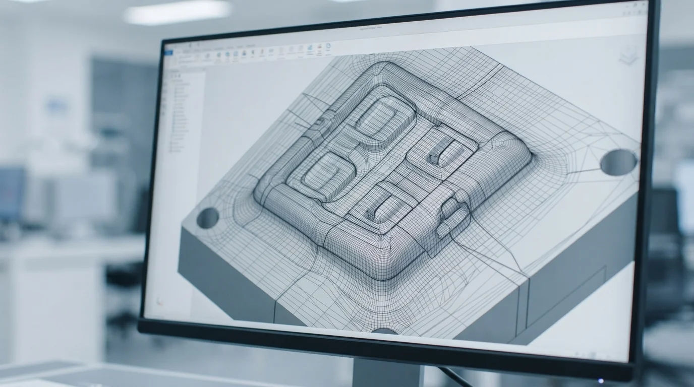
Table of Contents
1. Draft Angle Requirements for Soft Mold Core Release
2. Undercut Elimination and Manual Core Inserts
3. Rib Thickness and Uniform Cross Sections for Uniform Cooling
Draft Angle Requirements for Soft Mold Core Release
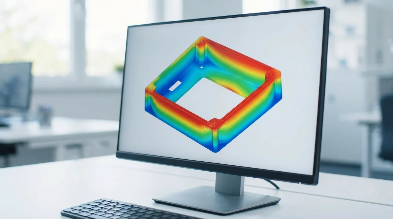
Question: Why do soft molds require larger draft angles than hard steel molds? Aluminum and pre-hardened soft steels are more prone to micro-galling and dragging, demanding at least 1.5 to 2.0 degrees of draft to prevent part scuffing during ejection.
Selecting appropriate mold metals directly influences injection molding cycle times and overall part dimensional stability during short-run production. Following smart mold-making rules ensures engineers select high-grade QC-10 Aluminum or soft P20 tool steel to construct cost-effective mold plates. Vertical features like reinforcing ribs and bosses must taper slightly to allow parts to release from core cavities cleanly. Zero-draft walls drag against core steel under high shrinkage pressures, creating visible scuff marks and deep stress cracks.
Draft angles represent a foundational design feature for injection molded plastic parts, preventing dragging and scuffing during ejection cycles. Implementing thorough design guidelines for bridge tooling ensures vertical ribs and bosses have adequate draft before permanent tools are cut. Boss diameters are generally reduced slightly toward the open face to maintain uniform wall thicknesses and prevent cosmetic sink marks. Sourcing early dimensional validation ensures these cored-out features hold critical thread-forming screws securely.
Undercut Elimination and Manual Core Inserts
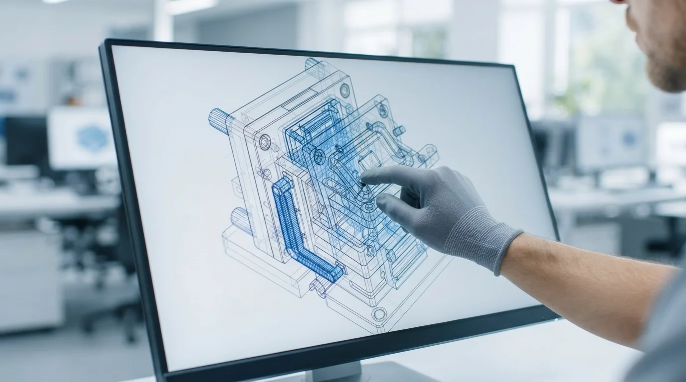
Question: How are tooling costs reduced for parts with complex undercuts? Replacing automatic hydraulic side-actions with manual hand-loaded core inserts simplifies mold construction, lowering mold fabrication expenses significantly.
Jucheng Precision supports mechatronics startups by delivering highly optimized, cost-saving fabrication options that protect development budgets from unnecessary expenses. Sourcing our expert 24-hour free DFM reviews helps product groups optimize gate placements, parting lines, and draft profiles before cutting metal or pouring silicone. Sourcing high-quality prototypes ensures your designs are built to withstand severe dynamic forces safely. Sourcing your components from our certified, single-roof manufacturing facility prevents communication errors, ensuring design changes are propagated across all stages safely.
Intricate internal undercuts and interlocking features require complex mechanical sliders or lifters inside injection molds, increasing tooling expenditures dramatically. Product developers utilize strategic design guidelines for bridge tooling to eliminate these undercuts by implementing simple sliding shut-offs. Designing simple split lines allows mold halves to open and close along a single axis, reducing overall mold complexity. Simplifying core features lowers initial capital requirements and accelerates tooling lead times.
Rib Thickness and Uniform Cross Sections for Uniform Cooling
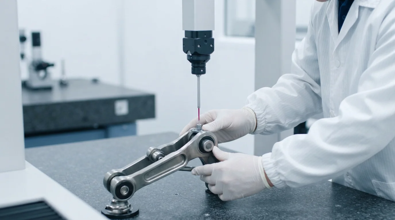
Question: What is the primary cause of cosmetic sink marks in injection molded components? Localized thick sections cool slower than surrounding thin walls, creating internal vacuum voids that pull surface polymer inward.
Maintaining uniform cross-sections represents the golden rule of plastic injection molding, preventing uneven volumetric shrinkage and post-mold warpage. Sourcing functional CNC Machining Service parts from extruded billets of ABS, Nylon (PA), or aluminum Polypropylene (PP) provides authentic material behavior before cutting Tool Steel core blocks. This detailed materials validation eliminates mechanical failure risks when transitioning prototype to production design configurations. Early validation prevents expensive engineering changes when scaling up to high-volume Injection Molding Service.
Meticulous parting line planning ensures seams are designed along natural sharp geometric boundaries to simplify post-mold cleanup. Molten polymer under high injection pressure can escape along split lines, forming thin plastic flash that requires manual de-flashing. Parting line shut-offs must be hand-fitted precisely to prevent flash formation on critical mating joints. This technical comparison table highlights baseline design parameters for CNC machining versus plastic injection molding:
| Manufacturing Parameter | CNC Machining Guideline | Injection Molding Guideline | Primary Engineering Reason |
|---|---|---|---|
| Minimum Wall Thickness | 0.8 mm (metals), 1.5 mm (plastics) | 1.2 mm to 3.0 mm | Prevent part deflection, ensure proper mold flow |
| Recommended Draft Angle | Zero draft permitted | 1.5° to 3.0° minimum | Prevent scuff marks, allow easy part ejection |
| Standard Tolerance | ±0.05 mm to ±0.01 mm | ±0.1 mm to ±0.15 mm | Match process repeatability, reduce tooling costs |
Partnering with an experienced Prototype Service specialist ensures your finished hardware matches the premium software experience. Sourcing your quotes manually ensures experienced engineers analyze your 3D STEP files to find additional ways of protecting your mold and maximizing your return on investment. Sourcing high-fidelity pre-production parts prevents tooling reworks and protects launch budgets. Sourcing your components from our certified, single-roof manufacturing facility prevents communication errors, ensuring design changes are propagated across all stages safely.
Frequently Asked Questions (FAQ)
What are the primary material advantages of rapid prototyping?
Understanding the baseline advantages of rapid prototyping allows mechatronics groups to bypass these high capital barriers safely during early development. Bypassing slow, manual mold-making procedures allows hardware developers to conduct dynamic fitment checks and aerodynamic wind tunnel tests immediately. Sourcing early DFM reviews simplifies split line layouts, eliminating the need for expensive mechanical sliders in rapid molds.
How can mold tooling expenses be reduced for short-run production?
Vacuum casting in silicone molds represents an excellent, low-cost method to manufacture twenty to fifty plastic enclosures cheaply. Sourcing custom polyurethane parts from silicone molds becomes highly cost-effective before investing in aluminum or soft steel cores. Product designers utilize Vacuum Casting to replicate production-grade polymer qualities, including flexible elastomer overmolding.
Does complex surface polishing increase overall manufacturing bills dramatically?
Manual hand-polishing, vapor-polishing, and multi-layer painting require intensive labor hours, which can double your overall project bill. Specifying standard bead-blasted or raw machine finishes for internal structures or early visual models lowers your total finishing expenditures. Product designers coordinate with manufacturing specialists to apply decorative coatings only on visible external show faces.

