


The bending section is the flexible distal assembly that lets an endoscope change direction, but it is not one undifferentiated tube. Its nested metal segments, joints, control wires, outer covering, and connections to neighboring assemblies must fit into a limited envelope while preserving the designed articulation. For manufacturing teams, that makes the endoscope bending section a coordinated set of components and interfaces rather than a single shape copied from a rendering. The term medical endoscope bending section manufacturing describes this drawing-led part and process scope; it does not replace the program’s approved design requirements.
This overview is intended for product engineers, sourcing teams, and suppliers reviewing custom component drawings. It discusses geometry, segmentation, material definition, process selection, and inspection evidence. It does not define clinical performance, sterilization validation, or regulatory acceptance. Those requirements depend on the finished device and its design controls; they must be supplied and approved by the responsible manufacturer.
Contents
- Read the bending section as an assembly stack
- Segment geometry sets the articulation envelope
- Specify materials by component and condition
- Match cutting and forming to the design stage
- Control wire paths and end connections
- Inspect the assembled relationship as well as parts
- Prepare a drawing package suppliers can evaluate
- Frequently asked questions
Read the bending section as an assembly stack
Begin with the complete distal assembly drawing and identify the bending section’s boundaries. Determine how it connects to the distal tip and the proximal tube, where the control wires pass, and which surfaces are covered after assembly. A component drawing may define a series of rings or slotted segments, but it may not show the tolerance stack that controls articulation. The assembly model helps distinguish features that are visible from those that become inaccessible once the section is built.
Separate the requirements for bending, attachment, and clearance. The design team should state the intended motion envelope and the interfaces that must be preserved; the supplier should not infer clinically meaningful motion from a loose part. If the geometry changes during development, keep part revisions tied to the assembly revision and sample build record. This is especially important when a change affects segment count, slot pattern, end geometry, or wire access, because nominally similar parts may assemble differently.
Segment geometry sets the articulation envelope
Many bending sections use a sequence of interconnected metal elements, sometimes made from a thin tube with slots or from separate rings. The chosen construction affects flexibility, joint contact, and the space available for wires and internal components. Review segment pitch, slot width, remaining bridge material, joint overlap, and end features as a coordinated pattern. The correct dimensions are design-specific. A supplier review can identify fragile features or tool access concerns, but it cannot replace the design authority’s required motion or durability criteria.
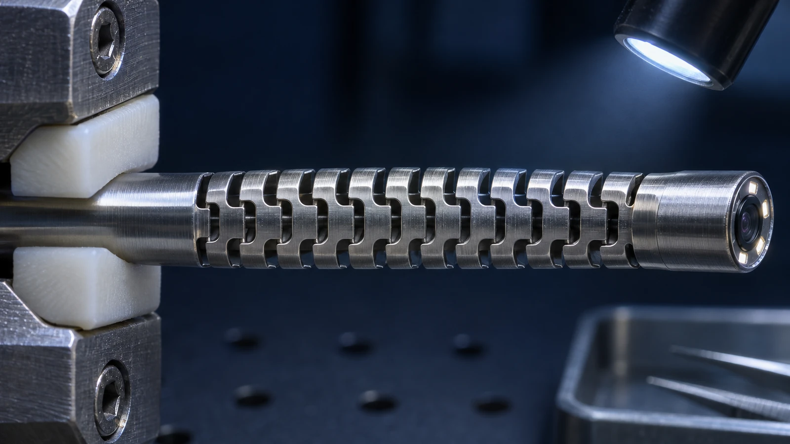
Pattern continuity deserves close attention. A burr, shifted slot, or inconsistent bridge can affect assembly and may create a local snag point. If a long sequence is cut from a tube, define how the datum is established along its length and how the part is supported during processing. If separate elements are assembled, define the orientation and end-to-end stack. Drawings should also show where the pattern starts and ends; otherwise, a supplier may make a correct repeating pattern with the wrong phase at the terminal feature.
Specify materials by component and condition
Material requirements can differ between the segmented structure, control wires, outer covering, and neighboring tubes. Specify each component separately, including grade, condition, surface state, and any traceability documents required by the device program. Stainless steel and other materials may appear in endoscope assemblies, but the appropriate choice depends on design requirements such as flexibility, strength, corrosion behavior, and joining method. A generic material name does not identify a complete procurement specification.
Where a material is still under evaluation, compare candidates against the actual design inputs rather than assuming one alloy or polymer is universally suitable. The process may alter surface condition or geometry; a finishing operation can remove material from a thin bridge, while joining heat can influence a nearby interface. Discuss the sequence with the designer and keep all change approvals documented. Do not claim biocompatibility, sterilization compatibility, or device approval from the material family alone; the finished-device manufacturer owns those validations.
Match cutting and forming to the design stage
Fine laser cutting can create closely spaced slots and repeated features in thin tubular components, while turning, milling, forming, or secondary finishing may be needed for end connections and mating surfaces. The process choice depends on the geometry, material, quantity, and required edge condition. For early prototypes, a route that allows controlled iteration may be preferable to optimizing a dedicated production sequence. For later stages, repeatability and documented inspection may become more central. Compare routes by the specific evidence they provide. Medical endoscope bending section manufacturing must account for how cutting, support, and edge finishing affect the specified segment pattern.
Thermal input, clamping, and tool access should be reviewed together. Thin walls can distort if unsupported, and a long slotted section may be less rigid than its solid starting tube. Plan how the part is held before the pattern is cut, and how it is protected during handling and cleaning. If a secondary process removes burrs or modifies the surface, define its limits so it does not alter slot dimensions or joint fit. A prototype supplier can discuss medical device manufacturing processes in relation to the drawing, but the device manufacturer specifies validation and acceptance requirements.
Control wire paths and end connections
Control wires and their anchors define how motion is transferred through the section. The drawing should identify wire passages, anchor locations, terminal geometry, and any clearance or bend constraints. A wire path that is only shown in an assembly illustration may not provide enough manufacturing information for the individual components. If an anchor is attached by a joining operation, define the joint location, surface preparation, inspection evidence, and any prohibited distortion near the bending elements.
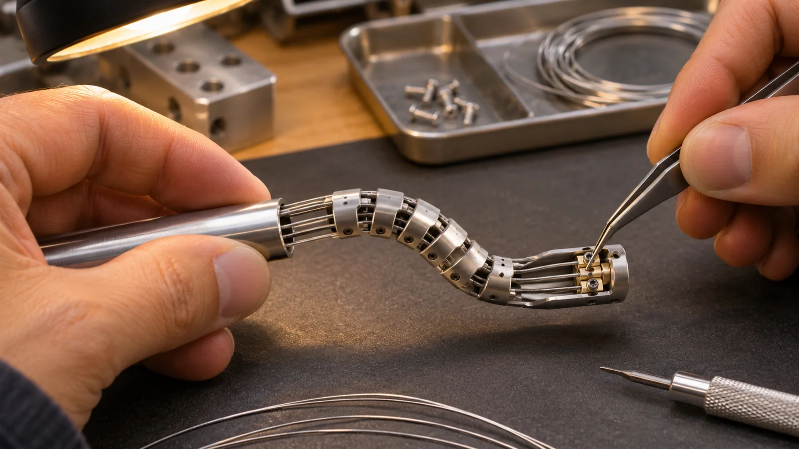
End connections are another common source of tolerance accumulation. The bending section must interface with adjacent assemblies without unintentionally changing the designed working length or orientation. Define reference faces and clocking features where necessary. If components are bonded, welded, or mechanically retained, include the method and process boundary in the controlled package. The supplier should not improvise a joint because two parts appear to fit on a bench; assembly acceptance depends on specified dimensions, materials, and process documentation.
Inspect the assembled relationship as well as parts
Part-level inspection may cover slot pitch, tube diameter, wall condition, end geometry, and burr limits. Those checks do not automatically establish the behavior of the assembled section. The device manufacturer should define any assembly-level evaluation, including the fixture, motion range, direction, and acceptance criteria. If the supplier is asked to report only dimensions, keep that report clearly separate from any functional or clinical validation claim.
Use measurement methods suited to small, repetitive features. Optical systems or magnified inspection may help evaluate slot edges and pattern consistency, while dedicated gauges may check selected diameters or interfaces. The drawing should identify sample frequency and critical characteristics. For a curved or flexible assembly, the fixture must avoid imposing an uncontrolled shape. Record revision, sample identity, material condition where applicable, and the measurement setup so results remain comparable across iterations.
Prepare a drawing package suppliers can evaluate
Provide part and assembly drawings, a 3D model, material specifications for each component, quantity and development stage, joining details, required finish, and inspection documents. Include the motion envelope or boundary conditions needed to understand the geometry, while identifying who owns functional verification. Flag features hidden after assembly and define whether in-process or final evidence is required for them. A medical endoscope bending section manufacturing package should identify the assembly boundary, component materials, joining scope, and who owns functional validation.
Ask for a supplier review that identifies thin features, difficult support conditions, edge-control risks, and any unclear datum transfer. Keep drawing requirements distinct from process suggestions. If the design is changing, provide revision status and a clear list of open decisions. This enables a prototype quotation to describe what it will make and inspect without implying that the supplier has validated the complete medical device.
For the wider process context, see medical device manufacturing processes; the device manufacturer remains responsible for product validation and acceptance requirements.
Frequently asked questions
Is the bending section one component?
It is usually an assembly of structural elements and interfaces. The drawing package should define the component boundaries and the requirements that apply after assembly.
Does a laser-cut sample prove articulation performance?
No. It can demonstrate selected geometry and support assembly evaluation. Motion and finished-device validation require criteria and methods defined by the device manufacturer.
Can a supplier recommend a material change?
A supplier can flag process concerns and provide information for a design review. Any material change must be approved and validated by the responsible design authority.

