


An electric motor end shield closes and supports one end of a motor assembly, but its manufacturing challenge is concentrated at a few connected interfaces. The bearing seat, housing register, mounting face, fastener pattern, and cable or cooling clearances all need to agree with the motor’s assembly datum scheme. A bearing bore that is locally accurate can still be misplaced relative to the register that centers the shield. That is why electric motor end shield machining should be planned around feature relationships rather than isolated dimensions.
This article covers custom end shields and end bells made to a customer-controlled drawing, including prototype and low-volume development parts. It does not prescribe motor performance, bearing fit classes, or universal tolerances. Those are design inputs. The manufacturing review should identify which geometry establishes alignment, what condition the material arrives in, and which measurements will demonstrate that the part matches the intended assembly.
Contents
- Identify the bearing and housing interfaces
- Build the datum chain from the installed motor
- Choose between a casting, billet, and prototype route
- Sequence machining to protect the bearing seat
- Keep material condition and thermal behavior in view
- Measure relationships, not just diameters
- What should an end-shield RFQ include?
- Frequently asked questions
Identify the bearing and housing interfaces
Begin by separating the bearing seat from the features that locate the shield to the motor housing. The drawing may include a register diameter or pilot, a mounting face, bolt holes, a bearing bore, and one or more reliefs. Mark which interface centers the shield, which controls axial position, and which carries the bearing fit specified by the designer. If the motor assembly drawing is available, use it to confirm the intended relationship rather than inferring it from the end shield alone.
Secondary features can be easy to overlook. A dowel hole may clock the shield; a bolt pattern may have clearance that does not itself establish concentricity; a cable opening can be a keep-out zone. A model review should distinguish functional datums from access and clearance geometry. That distinction helps the shop plan setups and helps the buyer assess whether a quote includes all relevant operations. The customer’s controlled specification should also identify any finish or coating that must be excluded from a seat or datum face.
Build the datum chain from the installed motor
Ask how the end shield is located on the motor body during assembly. A practical datum scheme often begins at the mounting face and register, then relates the bearing axis to those references. The precise scheme depends on the design and should not be invented by the supplier. However, if the drawing dimensions the bearing bore from one reference while the assembly locates the shield from another, request clarification before machining. Conflicting references create avoidable inspection disagreements. Electric motor end shield machining should preserve the bearing-seat axis relative to the register and mounting references defined for assembly.
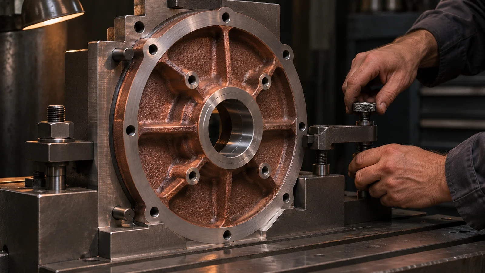
Concentricity, perpendicularity, and axial location may interact, so setup planning should preserve the intended relationships. If the bore and register are finished in separate operations, the drawing should make the relationship measurable and the process should control the transfer between setups. A fixture that references the same surfaces used in assembly can reduce ambiguity, but the appropriate method depends on geometry, blank condition, and volume. Do not translate a functional need into a tighter tolerance without design approval; first ensure the existing callout reflects the actual assembly requirement.
Choose between a casting, billet, and prototype route
A near-net blank may suit a design with ribs, bosses, and a relatively complex exterior. A billet can help during early development when geometry is changing and dedicated tooling is not justified. Neither route is automatically representative of the other: stock condition, internal structure, residual stress, and allowance strategy can differ. For an end shield prototype, specify whether the goal is interface fit, thermal evaluation, assembly access, or a manufacturing study. That purpose determines how much of the production route the sample needs to reproduce.
For cast components, ensure the machining stock is adequate at the register, bearing seat, and mounting face. For billet machining, review material removal and support of thin walls or ribs. If the final design requires a cast blank, a billet sample can validate selected geometry but cannot establish casting behavior. The site’s die casting process and prototype service pages provide process context; the drawing owner remains responsible for selecting the approved material and production specification.
Sequence machining to protect the bearing seat
Roughing and finishing should be considered separately when the shield has a large flange or thin web around its central bore. Heavy stock removal can release stress or allow the part to move under clamping. A balanced sequence may rough the main features, allow an agreed stabilization step if the material route calls for one, and finish the critical reference surfaces in a controlled setup. The actual route must be based on the blank, geometry, and drawing rather than a generic recipe.
Choose clamping points that support the part without distorting the register or bearing bore. The fixture should not force a flexible shield into an artificially flat condition unless the drawing defines that restraint for machining and inspection. Tool access to bolt holes, recesses, and internal reliefs should be reviewed early, especially if the housing has ribs that limit approach. Deburring around the bore and register requires particular care: an edge break should remove harmful burrs without altering the seat entrance beyond the drawing’s requirement.
Keep material condition and thermal behavior in view
End shields may be specified in different metals or alloys according to the motor design. The exact grade, temper or heat-treatment state, and any source documentation must come from the controlled drawing or purchase specification. Do not select a metal because it is common for a similar motor, and do not treat a generic material family as a substitute for a defined grade. The supplier can confirm what information is needed to source and process the blank.
Material and geometry also influence dimensional behavior during machining and assembly. A thin flange may respond to clamping; a dissimilar thermal expansion between shield, bearing, and motor housing can affect the design’s fit assumptions. These are engineering considerations for the product team and are not solved by changing a machining tolerance in isolation. When thermal or operating loads are relevant, provide the design conditions that govern the specified dimensions and keep acceptance criteria with the responsible motor engineer.
Measure relationships, not just diameters
A first-article plan should include the bearing-seat diameter and form as specified, but also its position and orientation relative to the mounting interface. Verify the register, mounting plane, bolt pattern, and clocking feature in a common datum reference where the drawing calls for it. A list of independent measurements may miss a relationship that only becomes visible when the shield is assembled. For complex geometry, a coordinate-measuring strategy can report selected points or profiles, but the method should be connected to the drawing requirements.
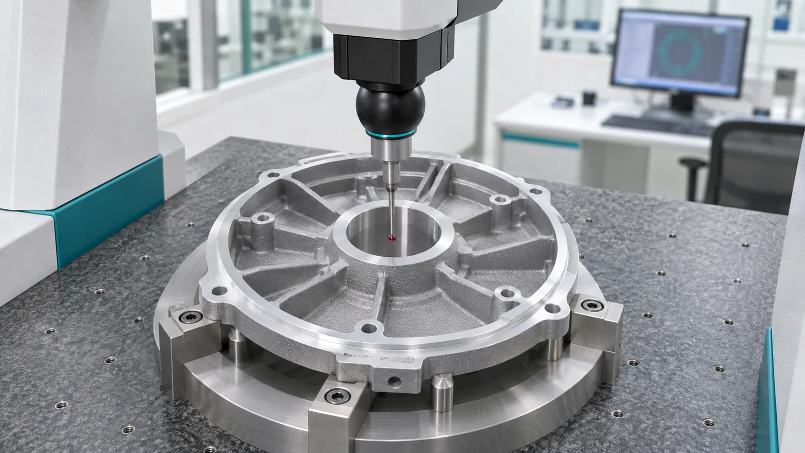
Record the measurement setup and part support. If a thin flange is clamped for inspection, the fixture contact points should be controlled and documented. If coating occurs after machining, agree which dimensions are measured before and after treatment, especially at the bearing seat and register. A report should identify the part, revision, material condition when applicable, method, and units. If the design requires a runout or alignment check, define the reference axis and setup instead of asking for an ambiguous “concentricity check.”
What should an end-shield RFQ include?
Include a controlled drawing, 3D model, blank material and condition, quantity profile, prototype or production stage, required surface treatment, and the expected inspection report. Mark the bearing seat, housing register, mounting face, and any features that establish clocking. State whether the blank is supplied by the customer or included in the quote, and identify operations that follow machining, such as coating or assembly. An electric motor end shield machining RFQ should call out whether the bearing seat, register, and mounting face are inspected in one datum plan.
Ask the supplier to list assumptions about machining stock, fixture references, post-process inspection, and any unclear tolerance relationship. If the design is evolving, distinguish released dimensions from features awaiting review. A drawing-based CNC machining discussion can then focus on actual interfaces rather than general equipment claims. The result is a more useful comparison between suppliers and a clearer plan for prototype learning.
For broader vehicle component context, see the automotive manufacturing processes overview; the part drawing still controls the material, geometry, and acceptance criteria discussed here.
Frequently asked questions
Is bearing-bore diameter enough to qualify an end shield?
No. The bore may also need a defined position and orientation relative to the motor housing interface. Follow the drawing’s datum scheme and inspection requirements.
Can a billet prototype prove a cast design?
It can answer selected envelope and assembly questions. It does not reproduce casting structure or all production-route effects, so record the validation limits.
Who specifies the bearing fit?
The motor design authority defines the fit and acceptance criteria. The supplier manufactures and reports the drawing-defined features and should raise ambiguity before production.

