


Calculating accurate short-run mold estimates requires a comprehensive understanding of raw billet volumes, G-code machine hours, and manual bench labor. Sourcing an itemized rapid tooling cost estimate enables product development groups to allocate capital efficiently before cutting core metal blocks. Automated web portals promise instant pricing algorithms, but raw digital calculations frequently ignore physical toolpath access directions and specialized post-processing steps. Sourcing human-engineered DFM reviews early ensures your 3D STEP files receive realistic quotes that reflect actual machine floor capabilities.

Selecting appropriate temporary manufacturing methods balances raw material properties with fast turnaround times during early-stage testing. Slicing complex three-dimensional CAD geometries precisely allows experienced toolmakers to analyze parting lines, draft angles, and wall thicknesses using advanced mold flow simulation software. Sourcing your components from an experienced partner ensures design changes are propagated across all stages safely. Let’s explore how automated estimators calculate baseline prices and why human DFM checks remain essential for hardware NPI.
Table of Contents
1. Key Variables in Estimating Mold Costs
2. Why Automated Cost Estimators Often Miss the Mark
3. How to Prepare Your 3D CAD for an Accurate Tooling Estimate
Key Variables in Estimating Mold Costs
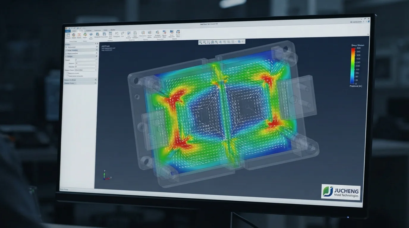
Question: What primary parameters dictate rapid mold pricing? Raw material billet volume, part geometric complexity, core undercut mechanics, and required surface finishes drive total mold invoices.
Understanding how an automated rapid tooling cost calculator generates baseline estimates helps engineering groups structure their CAD files for optimal manufacturing efficiency. Software algorithms measure total bounding box dimensions, part volumes, and surface areas within seconds to project raw material consumption and machine time. Simple geometries like uniform flat covers or cored-out boxes quote cheaply because automated systems predict fast 3-axis CNC milling toolpaths. Sourcing physical validation parts using standard geometries protects your starting developmental budgets cleanly.
Evaluating primary cost drivers during initial CAD modeling ensures your project budget remains highly controlled. Primary variables influencing short-run mold estimates include:
- Raw material block purchasing—Selecting aluminum AL7075 versus pre-hardened P20 steel plates establishes the baseline material investment
- Multi-axis machine spindle hours—Milling deep cavities, narrow rib slots, and angled lifter pockets drives active CNC hours
- Manual bench assembly and polishing—Fitting parting line shut-offs and hand-polishing cavity faces requires skilled toolroom labor
Why Automated Cost Estimators Often Miss the Mark
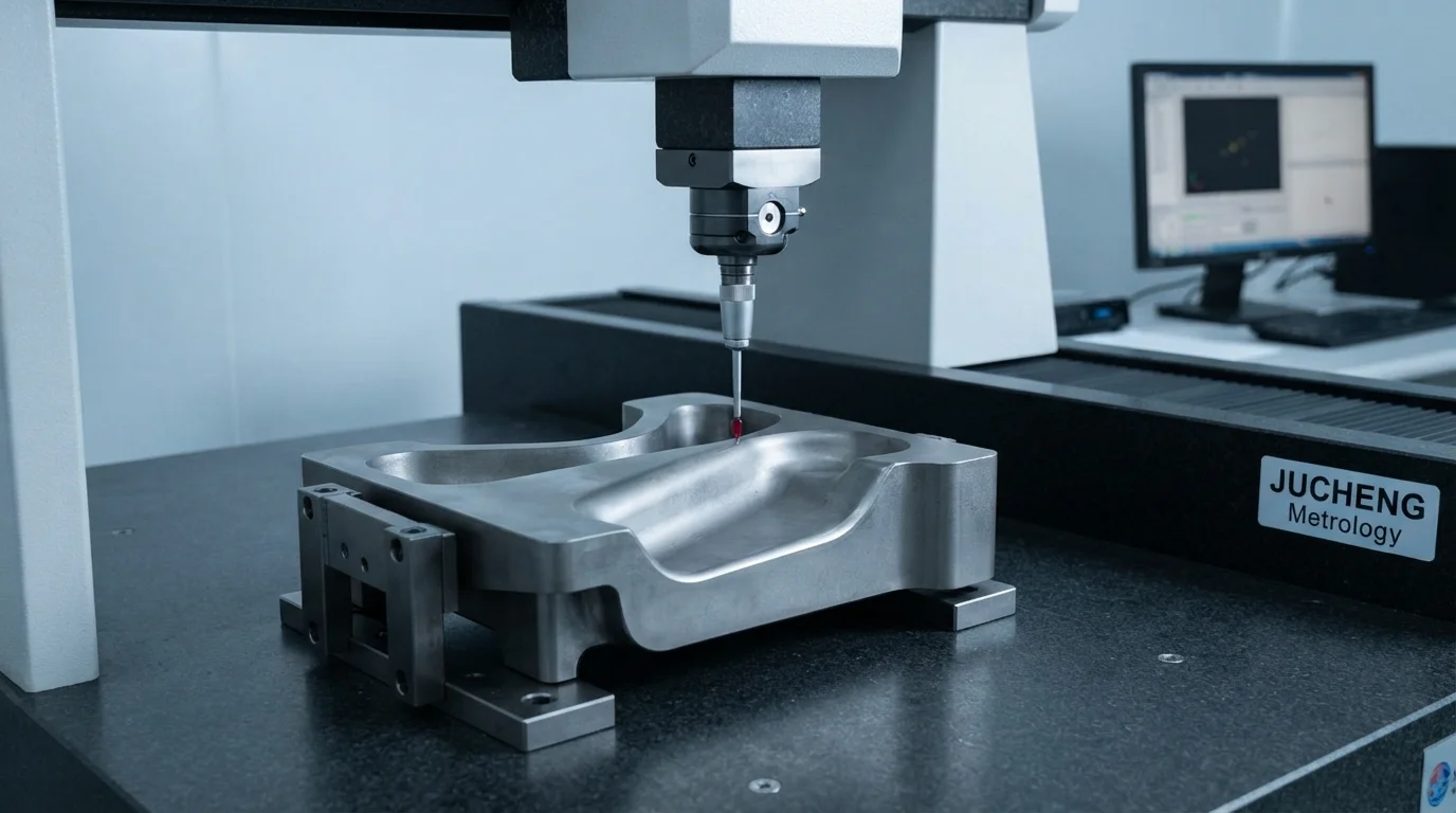
Question: Why do automated online estimators frequently give inaccurate quotes for complex parts? Software algorithms cannot evaluate manual hand-loaded insert labor, custom gating splay risks, or complex 5-axis clamping setups accurately.
Automated web portals apply conservative safety multipliers to complex geometries, inflating estimates to protect their operational margins against unexpected toolmaking hours. Undercuts requiring manual hand-loaded core inserts or complex parting line shut-offs confuse generic software algorithms completely. Sourcing functional CNC Machining Service parts or soft-metal molds requires human toolmakers to evaluate actual cutter access directions and clamping setups. Experienced engineers identify simple CAD tweaks that lower machining hours without altering functional part performance.
Sourcing functional parts molded from genuine engineering plastics like ABS, Nylon (PA), or Polycarbonate (PC) provides authentic material behavior under dynamic loading. This technical comparison table highlights baseline capabilities and limitations of automated algorithmic quoting versus expert human DFM reviews:
| Quoting Method | Turnaround Time | Evaluation Depth | Primary Engineering Advantage |
|---|---|---|---|
| Automated Online Calculator | Instant (Seconds) | Basic (Bounding box & volume only) | Fast baseline budgeting for simple geometries |
| Human Toolmaker DFM Review | 24 Hours | Exhaustive (Flow lines, gates, undercuts) | Uncovers hidden DFM cost-saving opportunities |
How to Prepare Your 3D CAD for an Accurate Tooling Estimate
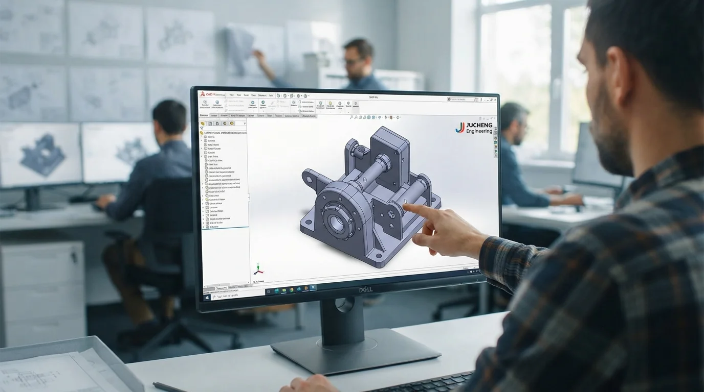
Question: What files are required to secure an accurate rapid tooling estimate? Providing a 3D STEP or Parasolid file along with a 2D PDF drawing detailing thread specs and critical tolerances ensures exact pricing.
Submitting clean 3D STEP or Parasolid files accompanied by a detailed 2D PDF drawing ensures toolmakers evaluate critical tolerances and thread specifications accurately. Sourcing an expert review of your CAD file through a rapid tooling cost calculator workflow ensures all geometric parameters are fully understood before cutting metal. Sourcing a dedicated Rapid Tooling Service using Aluminum or soft Tool Steel cores delivers genuine injection-molded components from production-grade resins within weeks. Sourcing rapid tooling allows product developers to validate gating, parting lines, and draft angles under real machine pressures.
Jucheng Precision supports mechatronics startups by delivering comprehensive 24-hour free DFM reviews that analyze draft angles, wall uniformity, gating locations, and shrinkage factors. Sourcing functional Prototype Service parts or soft-alloy molds allows engineering groups to validate designs before committing to high-volume production. Key steps to prepare your CAD files for accurate tooling estimates include:
- Convert files to STEP or Parasolid format—Exporting solid B-rep geometries preserves mathematical curves for precise CAM programming
- Attach a 2D PDF drawing sheet—Annotate tight tolerances, threaded hole pitches, and required surface roughness callouts clearly
- Specify exact resin grades and annual volumes—Providing target production quantities allows engineers to recommend optimal mold steel alloys
Partnering with a certified Injection Molding Service specialist ensures your finished hardware matches the premium software experience. Sourcing your quotes manually ensures experienced engineers analyze your 3D STEP files to find additional ways of optimizing your short-run molding budgets. Custom components undergo rigorous coordinate metrology checks to confirm exact dimensional compliance. Sourcing high-quality prototypes ensures your designs are built to withstand severe dynamic forces safely.
Frequently Asked Questions (FAQ)
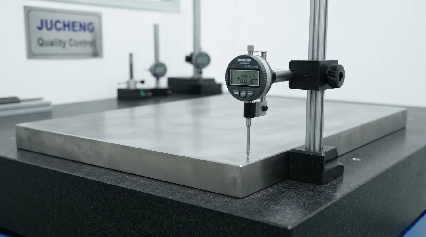
Why do online calculators give imprecise quotes for custom tooling?
Uploading CAD files to an online rapid tooling cost calculator provides a helpful baseline estimate within seconds, but human DFM reviews are necessary to confirm complex tooling details. Experienced engineers review moldflow fill fronts, ejector pin locations, and parting line shut-offs to deliver firm, production-ready pricing.
Why are 2D PDF drawing blueprints required alongside 3D models?
Providing a 2D PDF drawing alongside 3D STEP files is critical because 3D models do not contain thread pitch callouts or specific surface roughness specifications. Clear 2D annotations ensure toolmakers quote exact finishing labor and specialized tapping tools accurately.
How do hand-loaded inserts reduce initial mold fabrication costs?
Loose metal cores placed manually inside the mold cavity form undercuts economically without requiring expensive hydraulic sliders. Specifying hand-loaded inserts lowers initial mold fabrication expenses by thousands of dollars for short-run production.

