


Establishing realistic dimensional expectations represents a vital requirement when developing short-run injection molds for low-volume production. Sourcing functional plastic parts molded from soft aluminum or pre-hardened steel cores allows product teams to validate mechanical assemblies without overpaying for hard tool steels. Soft mold cavities, however, exhibit different thermal expansion rates and tool wear profiles compared to hardened H13 production steel. Aligning dimensional tolerances with process capabilities secures smooth assembly integration and reduces downstream tooling risks.
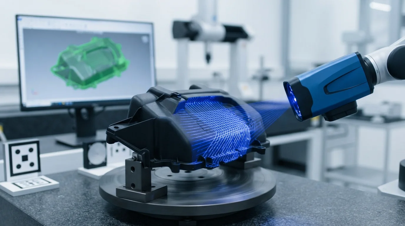
Adhering to strict design guidelines for rapid tooling ensures that target dimensional clearances remain achievable across diverse production runs. Slicing complex three-dimensional CAD geometries precisely allows experienced toolmakers to analyze parting lines, draft angles, and wall thicknesses using advanced mold flow simulation software. Sourcing your components from an experienced partner ensures design changes are propagated across all stages safely. Let’s explore baseline tolerance limits, tool wear variables, and metrology inspection protocols that guarantee short-run molding success.
Table of Contents
1. Standard vs Precision Tolerances in Low Volume Molding
2. Tool Wear Variables and Dimensional Drift Over Time
Standard vs Precision Tolerances in Low Volume Molding
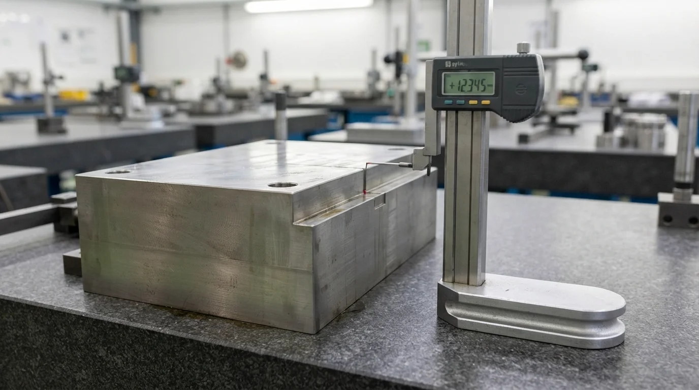
Question: What are the baseline tolerances for aluminum and soft steel rapid molds? Standard rapid tooling tolerances range from ±0.10 mm to ±0.15 mm, while precision multi-axis CNC milling can achieve ±0.05 mm on critical features.
Achieving tight fitments in multi-part hardware assemblies demands a deep understanding of baseline manufacturing variances across soft metal mold cores. Implementing reasonable rapid tooling tolerances during early design phases prevents physical interferences that lead to jammed mechanical joints or loose snap-fits. Sourcing custom components from a versatile Prototype Service ensures engineers utilize the physical accuracy of multi-axis milling. Subtractive machining avoids the thermal distortion issues of 3D printing, enabling operators to hold micro-tolerances with extreme repeatability.
Managing dimensional expectations across short-run molding cycles involves tracking several critical physical factors:
- Standard machining tolerances—Milled aluminum cavity blocks achieve baseline coordinate repeatabilities of ±0.05 mm straight off high-speed CNC spindles
- Thermal expansion offsets—Aluminum cores expand more under hot polymer flow than steel, requiring precise thermal water-channel temperature control
- Post-mold resin shrinkage—Polymers contract during cooling, altering final part dimensions based on volumetric shrinkage rates
Tool Wear Variables and Dimensional Drift Over Time
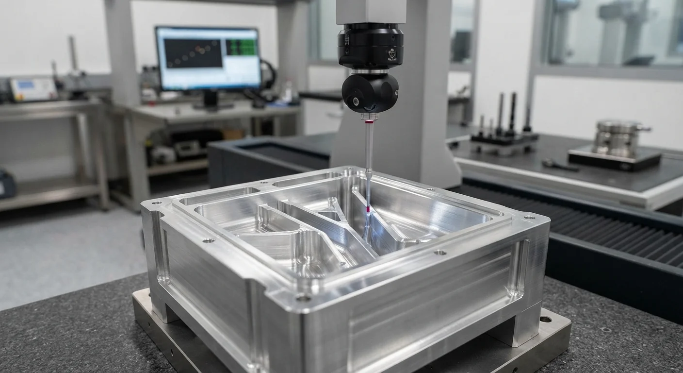
Question: How does tool wear affect dimensional stability in aluminum molds? Abrasive resins gradually erode aluminum gates and parting lines, causing dimensional drift and flashing after several thousand cycles.
Selecting appropriate mold metals depends heavily on whether your chosen polymer grade contains highly abrasive reinforcing fibers. Glass-filled polyamides or flame-retardant ABS polymers wear down soft Aluminum gates rapidly, causing dimensional drift over long runs. Tooling designers specify pre-hardened Tool Steel (like P20) for these abrasive materials to protect critical gate geometries. Sourcing functional parts molded from solid engineering plastics like Nylon (PA) or Polycarbonate (PC) provides authentic material behavior under dynamic loading.
Evaluating material physical properties helps engineers select the right alloy for core blocks, ensuring dimensions remain stable over thousands of cycles. Understanding how rapid tooling tolerances evolve over extended production runs helps teams schedule timely tool maintenance. This technical comparison table outlines baseline tolerance capabilities across different mold standards:
| Prototyping Technology | Baseline Dimensional Tolerance | Ideal Wall Thickness Range | Primary Engineering Application |
|---|---|---|---|
| CNC Machining | ±0.01 mm to ±0.05 mm | 1.0 mm to 10.0 mm | Bearing bores, sliding joint tracks, metal gears |
| Rapid Tooling (Aluminum) | ±0.10 mm to ±0.15 mm | 1.5 mm to 3.0 mm | Short-run enclosures, functional plastic trials |
| Production Tooling (H13 Steel) | ±0.05 mm to ±0.08 mm | 1.2 mm to 3.5 mm | Mass series production, extreme-volume scaling |
Zeiss CMM Metrology and Certified Quality Control
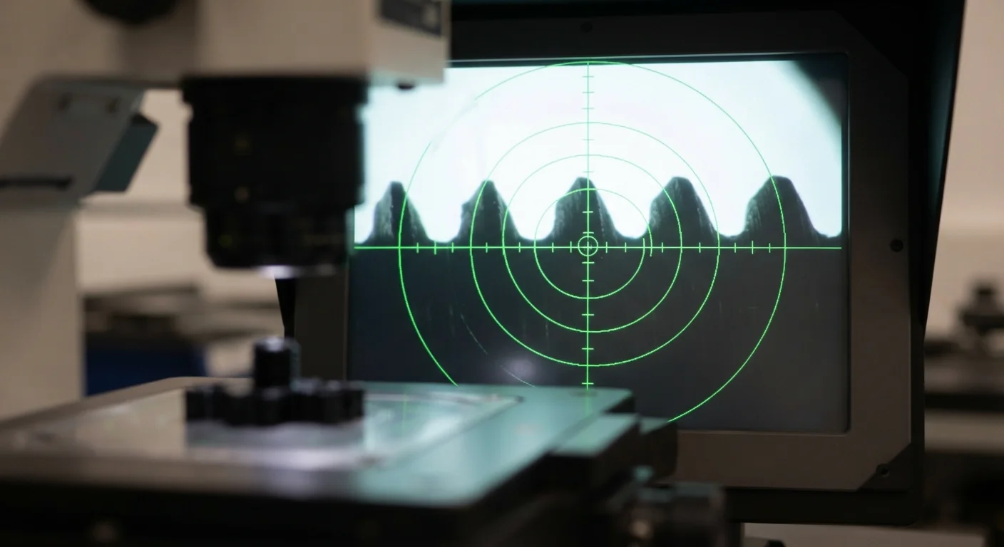
Question: How are micro-tolerances verified on short-run molded parts? Automated Zeiss Coordinate Measuring Machines inspect critical coordinate locations against digital CAD models inside temperature-controlled metrology labs.
Verifying dimensional compliance on complex molded enclosures requires advanced metrology tools that eliminate operator measurement errors. Sourcing a dedicated Rapid Tooling Service ensures that production samples undergo thorough inspection using automated Zeiss Coordinate Measuring Machines (CMM). Inspection specialists generate detailed dimensional reports to confirm compliance with ISO 9001, ISO 13485, and IATF 16949 quality management guidelines. Rigorous quality control guarantees that critical bearing bores and thread bosses line up perfectly during final assembly.
Jucheng Precision supports mechatronics startups by delivering comprehensive 24-hour free DFM reviews that analyze draft angles, wall uniformity, gating locations, and shrinkage factors. Sourcing functional CNC Machining Service parts allows engineering groups to validate designs before committing to aluminum or soft steel molds. Having thirty-five high-precision Injection Molding Service presses under certified quality management systems ensures your parts meet exact international specifications.
- Automated CMM probe sweeps—Multi-axis touch probes verify critical hole concentricities and surface profiles
- Optical comparator profile checks—Microscopic light projections inspect delicate thread pitches and internal snap contours
- Material mill certification reports—Chemical Certificate of Analysis (CoA) records verify raw metal billet purity
Frequently Asked Questions (FAQ)
What is the tightest tolerance achievable with rapid tooling tolerances?
Precision multi-axis CNC milling of aluminum mold inserts can achieve tolerances down to ±0.05 mm on critical features. Standard molded plastic part tolerances generally range from ±0.10 mm to ±0.15 mm due to polymer volumetric shrinkage variations.
Why does paint thickness affect final part dimensions?
Polyurethane paints and soft-touch clear coatings add a physical layer thickness of up to 0.15 mm per side to mating surfaces. Product designers must deduct this anticipated coating thickness from raw CAD clearances to prevent binding during final assembly.
How does mold temperature affect part dimensional stability?
Maintaining stable mold water line temperatures ensures uniform heat extraction across all cavity walls. Consistent cooling prevents localized internal stresses, eliminating post-ejection part warpage and dimensional drift.

