


A wafer chuck is the interface that holds a wafer or substrate in a defined position while semiconductor equipment performs a process or measurement. For a machined vacuum chuck or chuck base, the critical details may include a support plane, vacuum grooves or ports, mounting datums, locating features, and a path for connecting the chuck to the tool. A part can meet its outside dimensions yet fail its purpose if the support surface is uneven, the vacuum path is blocked, or the mounting pattern shifts the wafer relative to the process axis.
The phrase semiconductor wafer chuck machining can refer to several technologies and materials. This article is specifically about manufacturing considerations for drawing-defined machined chuck components and bases; electrostatic and ceramic chuck architectures may require different materials, processes, and supplier qualifications. The part sits within the broader semiconductor precision machining topic, but its acceptance requirements must come from the equipment design authority.
- Define what the chuck is locating and holding
- Control the support surface and datum stack
- Treat grooves and ports as a connected circuit
- Distinguish a chuck base from the complete chuck
- Select material and finish for the contact zone
- Verify flatness, location, and vacuum function separately
- Drawing and RFQ inputs for a machined chuck
Define what the chuck is locating and holding
Begin by identifying the substrate size and shape, the supported side, the contact area, and the intended holding method. A wafer, glass panel, film frame, or smaller coupon can impose different requirements. Specify whether the chuck must locate an edge, center a circular wafer, support a full surface, or leave selected regions open for inspection or processing. The equipment application determines the function; the machinist should not infer it from a circular outline.
Clarify how the chuck is mounted into the tool. Identify the machine datum, rotation axis, height reference, pin locations, and any adjustment mechanism. If the chuck is replaceable, define the repeatable locating interface and service procedure. If alignment is established during assembly, show how the measurement or adjustment is performed and what parts are included in the reference stack.
Also distinguish the component’s mechanical role from process performance. A machined base can provide a specified surface and vacuum passages, but wafer temperature, electrostatic force, process uniformity, or measurement accuracy depends on the complete equipment design and validation. Keep those system-level targets explicit so a dimensional inspection is not mistaken for proof of the whole process.
Control the support surface and datum stack
The support plane is often the most visible functional surface, but the drawing must say how it relates to the chuck mounting face, centerline, rotation axis, and locating features. Define the datum reference frame from the assembly. A surface that is flat in isolation can be tilted or distorted after mounting if the bolt pattern or backing structure is uneven.
Set tolerances according to the substrate and equipment requirement. Avoid specifying a very tight flatness or surface finish without linking it to the function, test method, and measurement area. A wafer contact surface may need a different inspection strategy from a mounting face or outer diameter. If the part is measured with a fixture, define the support points and clamping condition; otherwise measurement results can vary with setup.
Machining sequence should protect the functional plane from handling damage and distortion. Roughing, stress relief if required by the chosen material and design, finishing, and inspection may need to be coordinated. The actual sequence is case-specific, especially when the chuck has thin sections, deep channels, dissimilar materials, or large diameter relative to thickness.
Treat grooves and ports as a connected circuit
For a vacuum-held design, grooves, holes, internal passages, seals, and fittings form one circuit. The drawing should show how each branch connects, where the vacuum source enters, and which openings must remain isolated. A blocked passage, burr at a cross-drill, damaged seal land, or incorrect plug can alter holding behavior even if the outer dimensions are correct.
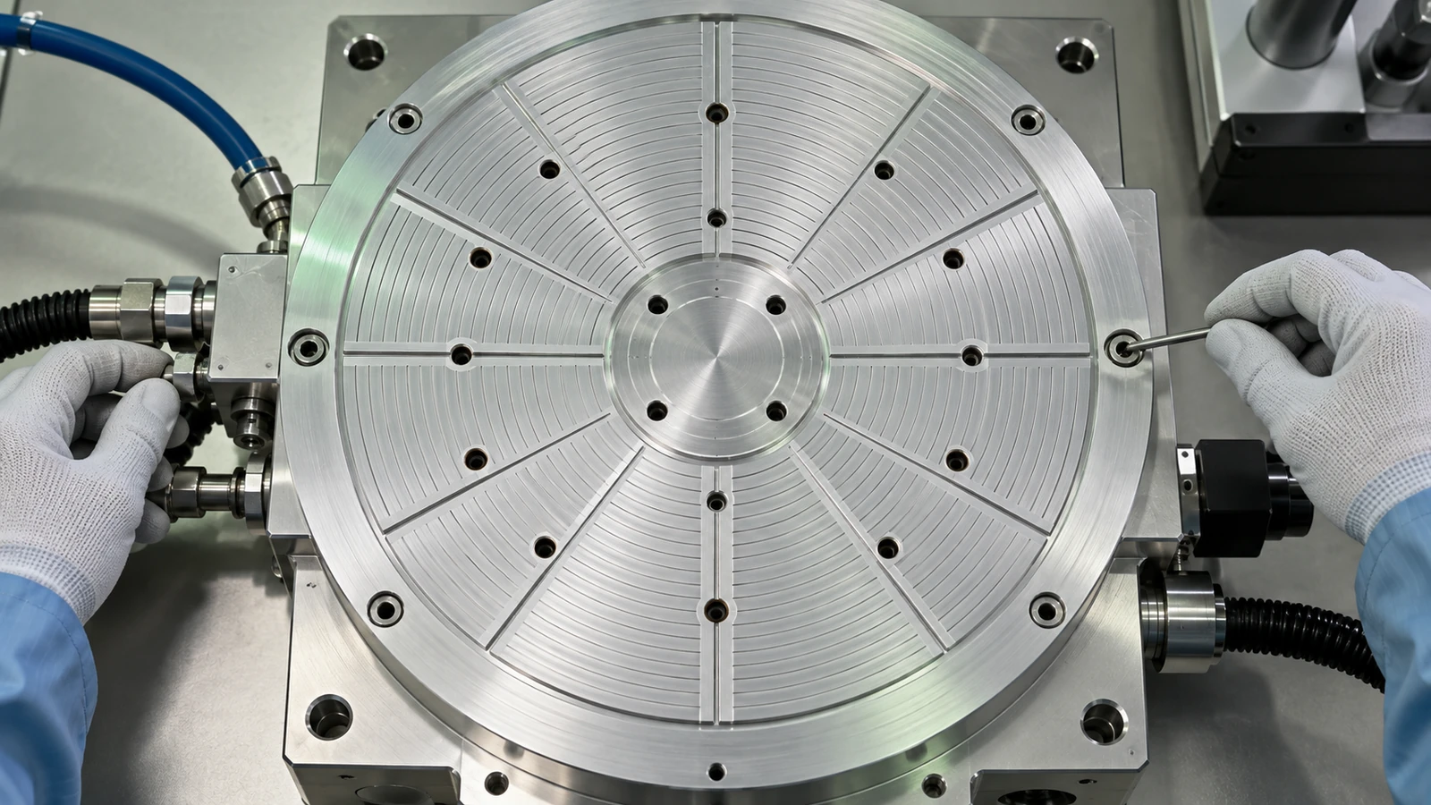
Review groove width and depth, port position, edge condition, and the surrounding support geometry together. Groove layout should follow the wafer or substrate interface and any keep-out zones supplied by the design authority. If the design uses a porous layer, replaceable insert, gasket, or separate cover plate, identify the boundary between the machined base and that component.
Do not rely on a generic leak-tight note. Define the test configuration, connection points, pressure or vacuum condition, duration, and acceptance criterion when a leak test is required. A leak check can verify the circuit under the specified setup; it does not by itself prove the wafer is held uniformly or that process results meet an equipment target.
Distinguish a chuck base from the complete chuck
A “wafer chuck” may describe a complete assembly with a support plate, electrode or heater, temperature sensors, vacuum circuit, wiring, and mounting hardware. A machine shop might be asked to produce only the metal base or a machined mounting plate. State the deliverable boundary clearly. This avoids confusion over whether electrical components, ceramics, embedded heaters, bonding, calibration, or final system testing are included.
The assembly may also contain a lapped surface, coating, bonded layer, insert, or replaceable contact component. These operations can change height and flatness and may require inspection after integration. Define which supplier owns each operation and who accepts the final stack. A drawing package that splits the mechanical base from the functional assembly should include interface dimensions and revision relationships.
For designs with a metal support and a polymer or ceramic contact layer, consider differential expansion, attachment method, contamination, and service life. If the chuck type relies on a specialized ceramic or electrical function, do not assume ordinary metal machining alone addresses that requirement. The manufacturing route must follow the approved architecture.
Select material and finish for the contact zone
Aluminum may be selected for a machined vacuum chuck base where low mass, thermal behavior, and accessible precision features are useful. Stainless steel can be relevant for other environmental or interface requirements. Engineering polymers such as PEEK may be used in selected support, insulation, or contact components, but temperature, creep, wear, moisture, and cleaning compatibility need review. These are candidate directions, not blanket material recommendations.
Specify the grade, condition, surface treatment, and any masking or cleanliness requirements. Anodizing or another coating may change dimensions or surface behavior, so identify the surfaces where the treatment is required and those where it is not permitted. If a contact surface must remain bare, define how it is protected during subsequent operations and handling.
For material background, review the site’s aluminum CNC machining page or PEEK machining information. The exact grade and finish should be selected from the equipment requirements, not from a generalized claim that one material is ideal for all wafer chucks.
Verify flatness, location, and vacuum function separately
A robust inspection plan separates at least three evidence types. Dimensional inspection checks the support plane, datum relationships, groove geometry, and mounting pattern. Vacuum testing checks the defined flow circuit and sealed boundaries. Functional evaluation checks the substrate interface and holding behavior in the specified assembly. Record the setup for each so the result can be interpreted and repeated.

Measurement of a large or thin chuck can be sensitive to supports, clamping, temperature, and instrument access. Specify the measurement area and the state in which the part is inspected. If the final assembly adds a cover, bonded layer, or thermal element, determine whether final inspection occurs before or after that operation. Keep reports linked to the part revision and material lot.
Particle control and packaging can matter even when dimensional measurements are complete. Define cleaning and protective handling requirements appropriate to the equipment program. A clean-looking outside does not demonstrate that internal grooves are free of residue, and a dimensional report is not a cleanliness certificate unless the method and criteria say so.
Drawing and RFQ inputs for a machined chuck
A useful RFQ includes the controlled model and drawing, substrate reference, machine datums, vacuum schematic, groove and port details, material grade, finish, quantity, revision, inspection plan, and any required cleaning or packaging instructions. Show the mating frame and relevant adjacent components. Identify whether the quote covers a base, a full mechanical assembly, or a prototype for fit and vacuum-path evaluation.
Ask for a review of tool access, thin sections, groove intersections, flatness after material removal, coating allowance, internal deburring, and measurement setup. If the chuck includes ceramics, heaters, electrodes, bonded layers, or calibrated functions, state who supplies and verifies those elements. This keeps the scope aligned with the actual assembly.
A dependable wafer chuck begins with a clearly defined substrate interface and an evidence plan matched to the intended function. Treat the support plane, vacuum circuit, mounting datums, material, finishing, and assembly as connected but separately verifiable parts of the design. That gives manufacturing and quality teams a concrete basis for making and reviewing the component.

