


Maintaining consistent cross-sectional geometries represents the foundational golden rule of short-run plastic part engineering, preventing uneven volumetric shrinkage and cosmetic splay. Sourcing an optimized wall thickness for rapid injection molding program protects your starting developmental budgets by avoiding localized polymer sink marks and severe post-mold warpage. Thick plastic hubs or solid bosses must be cored out and supported by thin reinforcing ribs to ensure consistent polymer solidification throughout the molding cycle. Slicing complex three-dimensional CAD geometries precisely ensures early-stage parts release cleanly from core cavities without scuffing or warping. Sourcing these low-volume parts preserves crucial development cash flow, avoiding the massive capital expenditure associated with traditional hard steel molds.
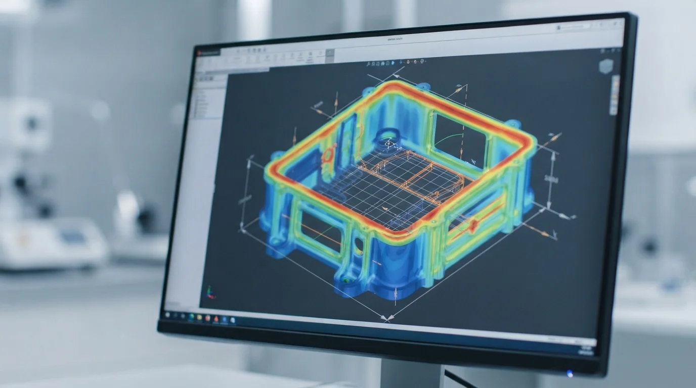
Table of Contents
1. Uniform Wall Principles and Sink Mark Prevention
2. Recommended Thickness Ranges for Common Engineering Resins
Uniform Wall Principles and Sink Mark Prevention
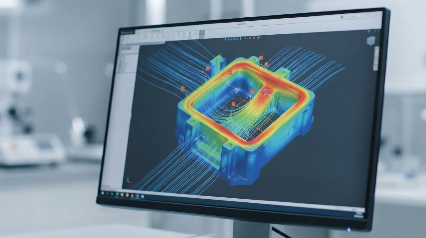
Question: What causes cosmetic sink marks on show faces? Localized thick sections cool slower than surrounding thin walls, creating internal vacuum voids that pull surface polymer inward.
Molten plastic injected under high pressure shrinks as it cools against cold mold cavity walls, demanding uniform heat extraction to maintain flat surfaces. Sourcing a dedicated Rapid Tooling Service using aluminum or soft steel cores delivers genuine injection-molded components from production-grade resins within weeks. Slicing CAD files precisely allows experienced toolmakers to analyze parting line shut-offs manually. Symmetrical component designs simplify holding fixtures, reducing initial setup labor hours dramatically.
Adhering to strict design guidelines for rapid tooling ensures that target dimensional tolerances remain realistic across different manufacturing processes. Tight tolerance expectations must be balanced carefully against physical material capabilities to avoid unnecessary machining setups. Sourcing functional parts molded from solid engineering plastics provides authentic material behavior under dynamic loading. Sourcing high-quality billet metals protects your developmental budget from material premium markups.
Recommended Thickness Ranges for Common Engineering Resins

Question: What is the optimal wall thickness range for plastic injection molding? Most engineering thermoplastics perform best with wall thicknesses between 1.5 mm and 3.0 mm to balance structural strength with fast cooling cycles.
Selecting appropriate wall thickness for rapid injection molding projects involves balancing raw resin flow lengths with target cycle speeds. Amorphous polymers like ABS or Polycarbonate (PC) flow predictably across walls between 1.5 mm and 3.0 mm. Semi-crystalline resins like Nylon (PA) or Polypropylene (PP) require tighter thickness control due to higher volumetric shrinkage rates. Sourcing accurate resin datasheets prevents dimensional discrepancies on critical mating features.
Evaluating material physical properties helps engineers select the right wall parameters, ensuring dimensions remain stable over thousands of cycles. This technical comparison table outlines recommended wall thickness ranges across common molding resins:
| Resin Type | Recommended Wall Thickness Range | Volumetric Shrinkage Rate | Primary Engineering Benefit |
|---|---|---|---|
| ABS (Medium Impact) | 1.2 mm to 3.5 mm | 0.4% to 0.7% | Excellent dimensional stability, low warpage risk |
| Polycarbonate (PC) | 1.5 mm to 3.0 mm | 0.5% to 0.8% | High impact strength, optical clarity options |
| Nylon 6 (PA6-GF30) | 1.5 mm to 3.0 mm | 0.3% to 0.6% | Outstanding structural rigidity, high heat resistance |
| Polypropylene (PP) | 0.8 mm to 3.5 mm | 1.5% to 2.5% | Exceptional chemical resistance, high living-hinge fatigue life |
Transitioning Wall Sections and Smooth Geometry Steps
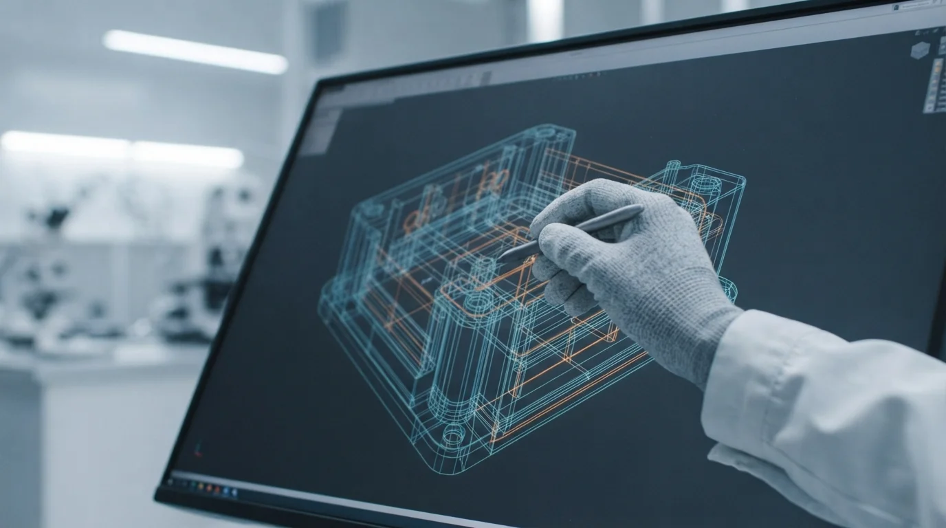
Question: How should wall thickness transitions be designed? Tapering thick-to-thin section steps gradually with a 3:1 chamfer or radius prevents localized stress concentration and internal air traps.
Jucheng Precision operates a fully-integrated factory setup containing both multi-axis machining centers and precision injection molding presses. Factory engineers deliver comprehensive 24-hour free DFM reviews to optimize gate locations, parting lines, and draft profiles before cutting metal. Sourcing functional CNC Machining Service parts or Vacuum Casting models allows engineering groups to validate designs before committing to aluminum or soft P20 steel molds. Having thirty-five high-precision molding presses under certified quality management systems ensures your parts meet exact international specifications.
Partnering with a certified Injection Molding Service specialist ensures your finished hardware matches the premium software experience. Sourcing your quotes manually ensures experienced engineers analyze your 3D STEP files to find additional ways of optimizing your wall thickness for rapid injection molding parameters. Sourcing a high-fidelity Prototype Service ensures your finished hardware matches target mechanical specifications. Sourcing high-quality prototypes ensures your designs are built to withstand severe dynamic forces safely.
Frequently Asked Questions (FAQ)
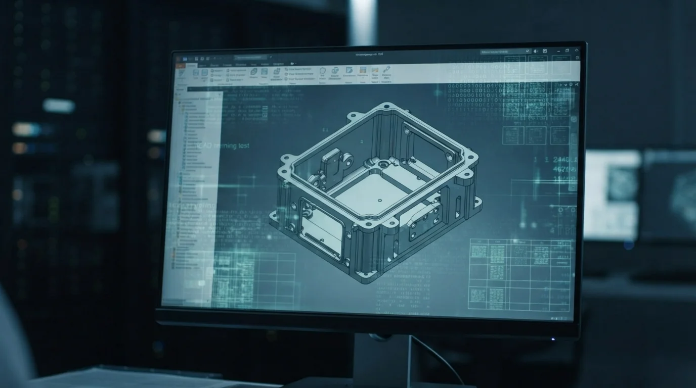
What is the optimal wall thickness for structural plastic enclosures?
Molded or milled plastic enclosures typically perform best with a wall thickness of 1.5 mm to 3.0 mm. Sizing walls within this range balances mechanical impact resistance with general polymer flow characteristics and cooling speeds.
How are thin-walled CNC metal parts machined without warping?
Standard multi-axis CNC milling and high-resolution stereolithography SLA processes can deliver fully validated physical mockups within 3 to 5 business days. Bypassing slow manual mold-making procedures allows hardware developers to conduct dynamic fitment checks and aerodynamic wind tunnel tests immediately. Sourcing your prototypes from a turnkey manufacturer ensures experienced mold makers suggest smart gate placements.
Why do uneven walls cause plastic prototypes to warp?
Most silicone molds yield twenty to thirty clean pulls before the rubber becomes brittle and begins to tear. Designing parts with gentle draft angles and generous fillets helps preserve the cavity walls, extending mold life up to forty runs. Sourcing early DFM reviews simplifies split line layouts, eliminating the need for expensive mechanical sliders in rapid molds.

