


Achieving proper fitment in multi-part hardware assemblies demands a deep understanding of baseline manufacturing variances across diverse fabrication processes. Establishing realistic rapid prototyping tolerances during early development cycles prevents physical interferences that lead to jammed mechanical joints or loose, vibrating snap-fits. Product engineers frequently make the mistake of assigning machined-metal clearances to additive polymer parts, resulting in immediate prototype failure. Aligning dimensional expectations with process capabilities secures smooth assembly integration and reduces downstream tooling risks.
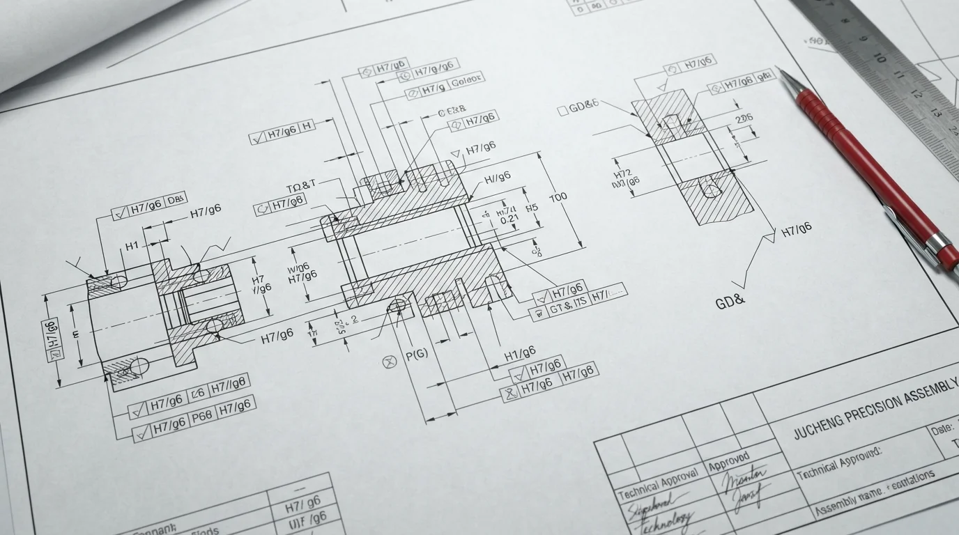
Sourcing physical validation models with precise dimensional feedback helps mechatronics groups confirm theoretical design calculations realistically. Metrology specialists evaluate critical bearing bores, sliding tracks, and interlocking cover gaps using high-accuracy Coordinate Measuring Machines. Resolving dimensional deviation risks during early mock-up phases ensures the physical hardware functions exactly like series-production injection molded components. Technical design groups secure pristine aesthetics and flawless assembly kinematics by addressing process boundaries systematically.
Table of Contents
1. Baseline Expectations and Additive Manufacturing Limits
2. Micro Precision Capabilities through Multi Axis CNC Machining
Baseline Expectations and Additive Manufacturing Limits
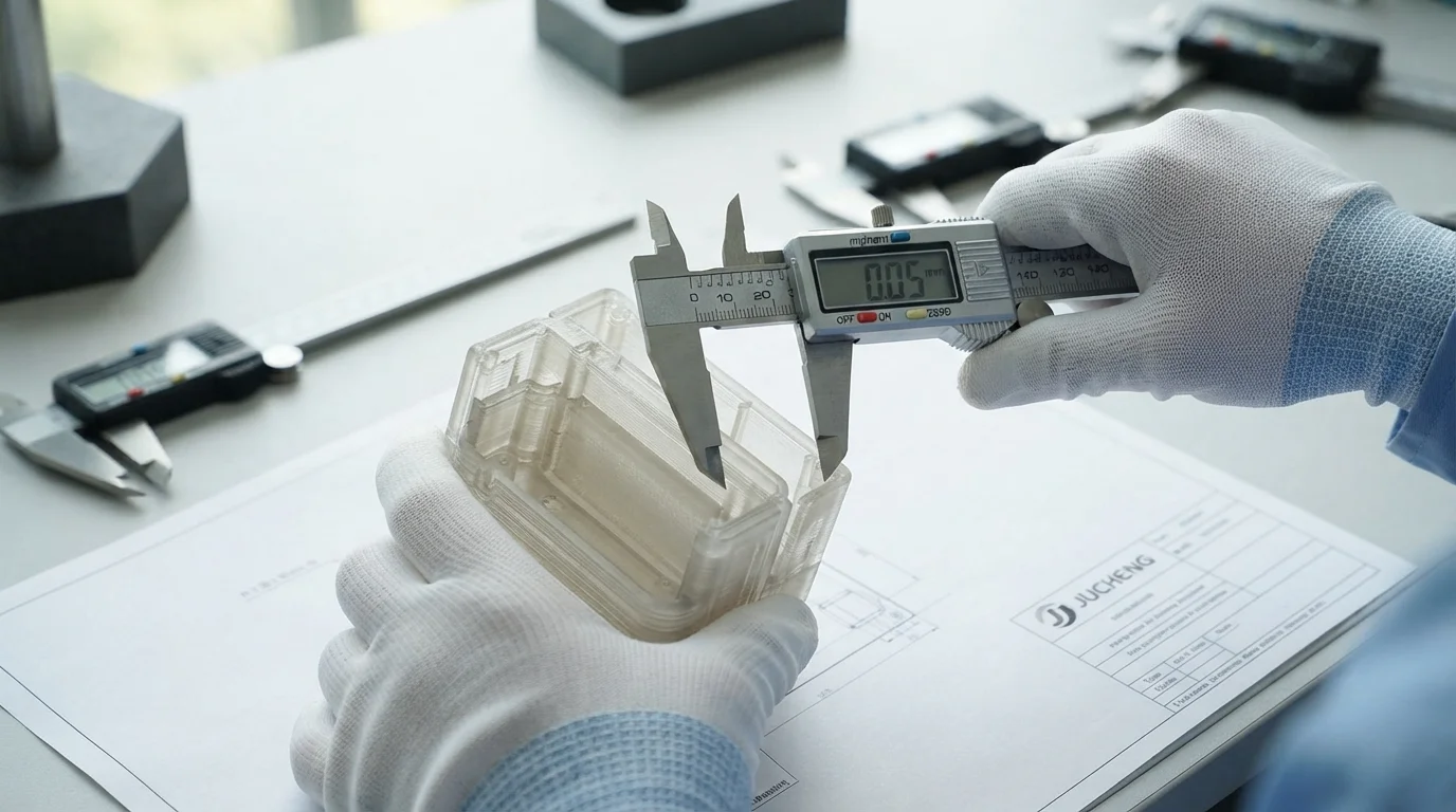
Question: What is the typical baseline tolerance for 3D printed polymer parts? Photopolymer SLA and powder-bed SLS printing typically achieve dimensional tolerances of ±0.15 mm to ±0.20 mm depending on part geometry.
Additive manufacturing technologies offer remarkable design freedom, yet thermal shrinkages and layer-stacking physics impose clear dimensional boundaries. Photopolymer resins utilized in stereolithography (SLA) contract as they cure under UV laser sweeps, causing subtle dimensional deviations on large flat surfaces. Powder-bed fusion methods like selective laser sintering (SLS) suffer from localized heat-induced warpage as raw materials cool unevenly. Structural designers must account for these baseline polymer limitations to prevent assembly mating issues.
Sourcing early mock-ups requires designers to allocate generous clearances around interlocking snap-fits and cored-out button bosses. Adhering to generous baseline limits ensures that 3D printed housings assemble cleanly without requiring manual filing or sanding. Understanding the baseline limits of rapid prototyping tolerances prevents engineering teams from specifying impossible micro-clearances on additive parts. Early dimensional allowances ensure different plastic parts mate together seamlessly during form and fit validation.
Micro Precision Capabilities through Multi Axis CNC Machining
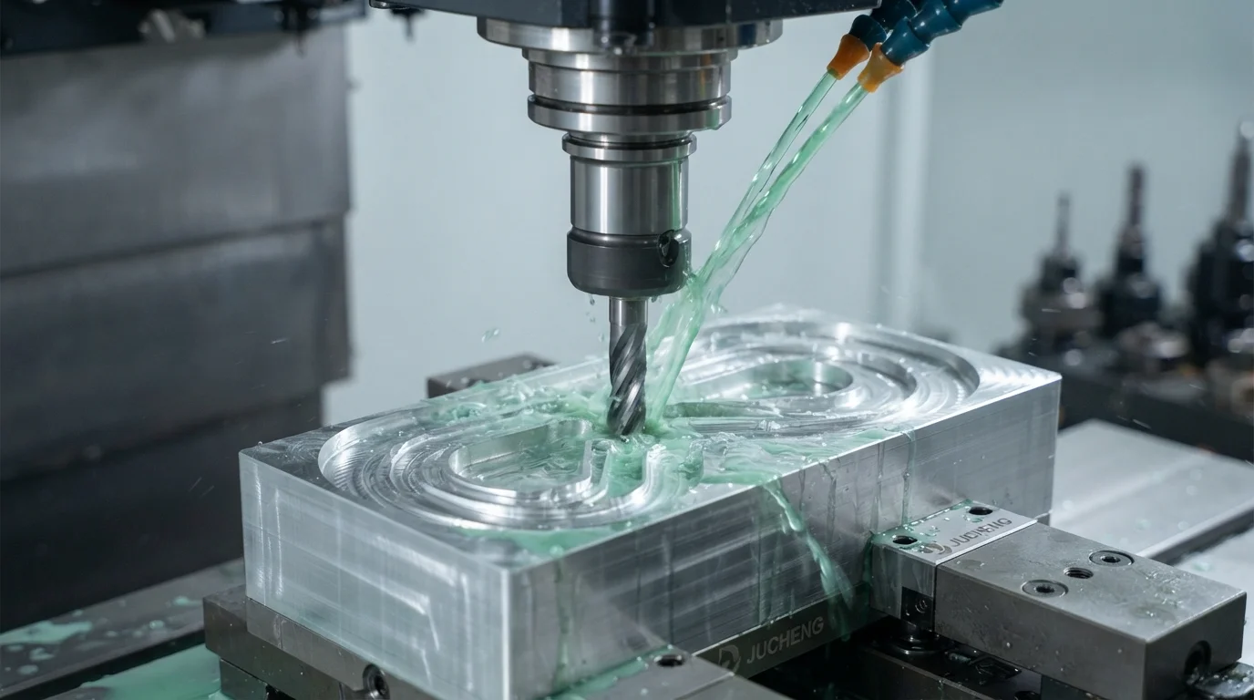
Question: Why is CNC machining preferred for high-precision bearing bores? Subtractive milling can reliably achieve micro-tolerances down to ±0.01 mm, preventing radial play in mechanical joints.
Precision mechanical assemblies requiring airtight seals, rotating shafts, or sliding linkages demand dimensional repeatabilities that additive methods cannot deliver. Implementing thorough rapid prototyping design principles ensures critical structural mounting plates are routed on multi-axis CNC milling centers. Subtractive machining avoids the thermal distortion issues of 3D printing, enabling operators to hold micro-tolerances with extreme repeatability. Standard machined clearances prevent internal components from buckling under dynamic load configurations.
Selecting the correct manufacturing process involves balancing dimensional tightness with overall tooling expenditures. High-precision medical, automotive, and aerospace prototypes are milled from solid billet blocks to preserve isotropic material properties. This technical comparison table outlines baseline dimensional limits across standard rapid fabrication methods:
| Prototyping Process | Baseline Dimensional Tolerance | Ideal Wall Thickness Range | Primary Engineering Application |
|---|---|---|---|
| CNC Machining | ±0.01 mm to ±0.05 mm | 1.0 mm to 10.0 mm | Bearing bores, sliding joint tracks, metal gears |
| SLA 3D Printing | ±0.15 mm to ±0.20 mm | 1.5 mm to 3.0 mm | Visual display mock-ups, cosmetic form studies |
| Vacuum Casting | ±0.20 mm to ±0.30 mm | 2.0 mm to 4.0 mm | Elastomer soft-touch grips, colored enclosures |
Optimizing mechanical tolerances allows engineers to evaluate functional clearance boundaries before committing to permanent steel molds. Generous radius values allow standard endmills to cut profiles quickly without inducing tool vibration or deflection. Mechanical designers lower manufacturing expenses by designing parts that fit standard cutting tool diameters.
Post Processing Coatings and Surface Treatment Offsets
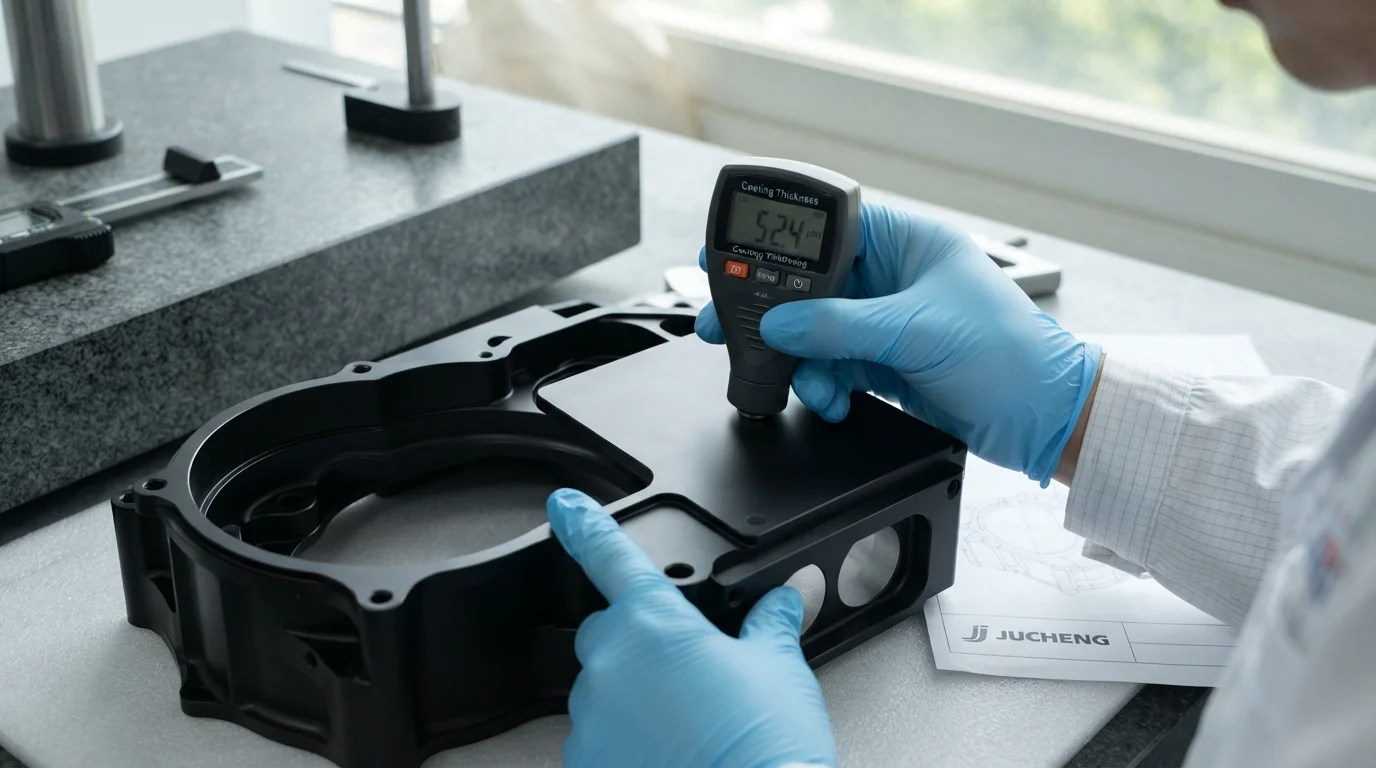
Question: How do surface coatings affect engineered prototype dimensions? High-thickness polyurethane paints and anodizing build-ups add measurable micro-layers that must be deducted from raw CAD dimensions.
Applying cosmetic or functional surface treatments represents a major variable that directly alters finished component dimensions. Paint coatings, soft-touch spray coatings, and thick polyurethane paints add visible layers ranging from 0.05 mm to 0.15 mm per side. Failing to account for these post-processing build-ups results in tight interlocking parts binding or failing to assemble entirely. Technicians compensate for coating thicknesses during early machining setups by backing off critical dimension dimensions.
Anodizing aluminum parts also creates a surface layer build-up of aluminum oxide that must be modeled during development. Technical review groups analyze anodizing thicknesses carefully to prevent thread-forming screws from binding in tapped holes. Managing these complex offsets through precise rapid prototyping tolerances prevents dimensional discrepancies during final lab assemblies. Sourcing comprehensive engineering support ensures all cosmetic and mechanical offsets are fully resolved before cutting raw metal.
Jucheng Precision operates a fully equipped manufacturing facility containing 150+ CNC machines, including 25 high-precision 5-axis Haas/Mazak systems to mill complex linkages. Factory teams deliver comprehensive 24-hour free DFM analyses to resolve draft angles, wall margins, and post-coating offsets before fabrication begins. Specialized rapid tooling molds deliver high-quality injection-molded components within 4 to 15 days, helping design groups hit aggressive launch schedules. Operating under a strict no-MOQ policy enables mechatronics groups to refine customized hardware variations safely.
Frequently Asked Questions (FAQ)

What is the tightest tolerance achievable for a rapid prototype?
Multi-axis simultaneous CNC milling centers achieve pristine tolerances down to ±0.01 mm in aluminum and stainless steel. Specialized micro-machining setups maintain micro-tolerances for critical bearing bores and internal gear threads easily.
Why does paint thickness cause assembly failures in prototype enclosures?
Polyurethane paints and soft-touch clear coatings add a physical thickness of up to 0.15 mm per side to mating surfaces. Product designers must deduct this anticipated coating thickness from raw CAD clearances to prevent binding during assembly.
How are dimensional tolerances verified before delivery?
Metrology specialists verify critical dimensions using high-accuracy automated Coordinate Measuring Machines and optical comparators. Inspection teams generate comprehensive dimensional reports to confirm compliance with ISO 9001 and IATF 16949 standards.

