


A panel is part of the vehicle architecture
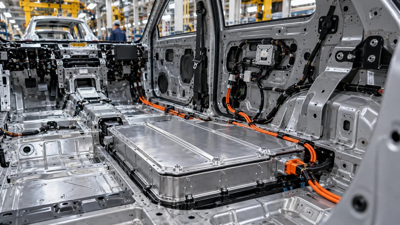
The correct panel design begins with its neighbors. A cover may need to seal a compartment, keep road debris away from electronics, guide cooling air, reduce noise, or provide a service opening. A body panel may be judged by gap and flush, while an underbody panel may be judged by clearance, stiffness, and resistance to impact. These are different engineering jobs even if both start as sheet stock.
Before the flat pattern is finalized, identify the interfaces that cannot move. Mark fastener locations, sealing lines, locating features, cable passages, drain paths, and areas that require tool access. This map gives the fabricator enough context to recommend bends, reliefs, weld locations, and inspection datums.
Separate appearance from function
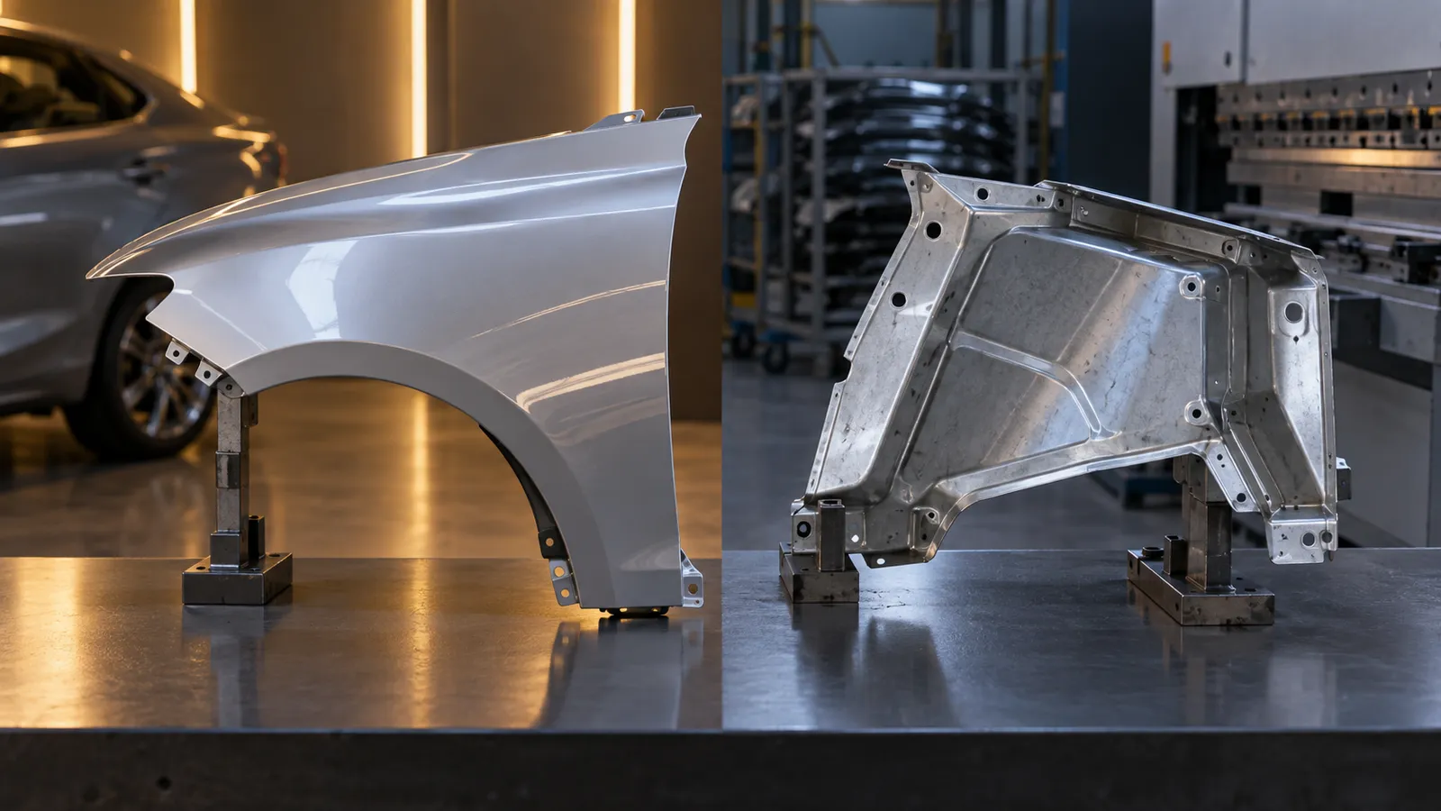
Visible automotive sheet metal panels need controlled edges, consistent surface condition, and a finish that supports the intended appearance. Hidden panels may prioritize corrosion protection, stiffness, serviceability, or cost. Mixing those expectations into one vague “good appearance” requirement makes both quoting and inspection subjective.
| Panel requirement | Typical evidence | Design implication |
|---|---|---|
| Visible exterior surface | Color, texture, gap, and flush review | Protect the surface and control cosmetic edges |
| Electronic enclosure wall | Fit, sealing, grounding, and coating check | Plan interfaces, masking, and service access |
| Heat or debris shield | Clearance and environmental validation | Control shape, material, and attachment method |
| Interior support panel | Fit, stiffness, and tactile edge review | Use safe edges and repeatable locating features |
Documenting the priority prevents an inexpensive prototype from being rejected for a requirement it was never meant to prove, while also preventing a cosmetic panel from being treated like an ordinary hidden bracket.
Use form to create stiffness
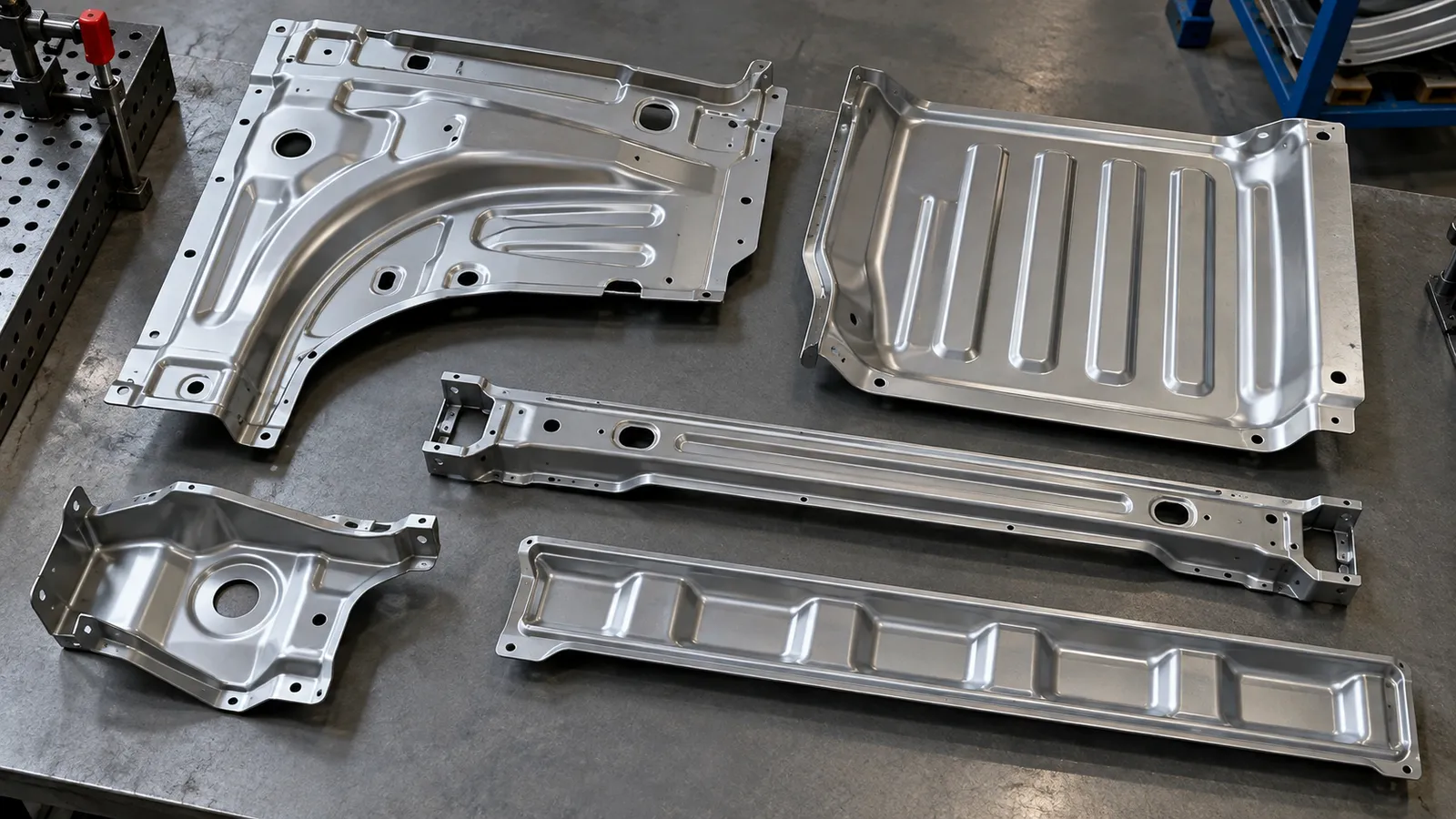
Flat sheet is efficient but flexible. Bends, beads, ribs, joggles, hems, and formed channels increase stiffness by changing the section geometry. The best feature depends on available space, load direction, tooling access, and the appearance of the finished panel. A bead may add rigidity without a large mass increase. A flange may improve both stiffness and attachment. A hem can protect an edge but also add a second layer that affects clearance.
Stiffness features should be reviewed with the forming route. A deep or narrow channel may be difficult to produce with a standard press-brake tool. A drawn feature may require dedicated tooling and controlled material flow. For low-volume programs, a sequence of bends and welded reinforcements may be more economical than a complex draw die. The objective is a stable panel, not a particular process name.
Edges, holes, and joining features
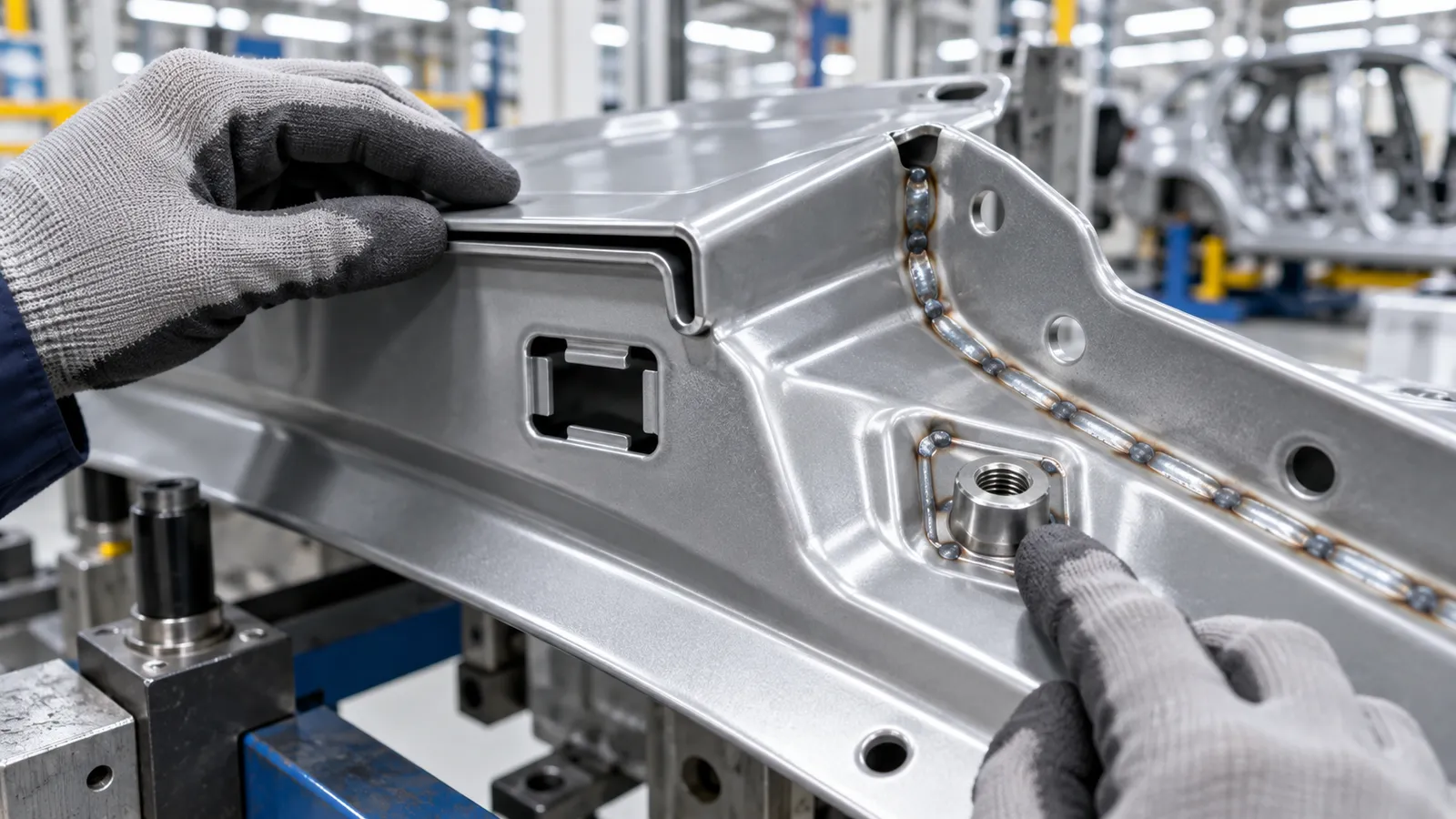
Panel failure often starts at a small feature. A hole too near a bend can distort. A sharp laser-cut edge can damage a harness. A slot without adequate relief can create a crack or stress concentration. A fastener opening may be dimensionally correct but impossible to reach with the installation tool.
Define edge treatment according to location. Exposed edges may need a hem or generous radius. Hidden edges may only need deburring. Grounding points, weld flanges, clips, and sealing surfaces should be identified as functional features. This distinction helps the supplier select cutting, forming, welding, hardware insertion, and finishing steps in the right order.
Joining also affects panel geometry. Spot welding, laser welding, riveting, clinching, threaded inserts, and mechanical fasteners each add different access and distortion concerns. A prototype assembly is often the fastest way to reveal whether the selected joint can actually be installed.
Material and corrosion decisions
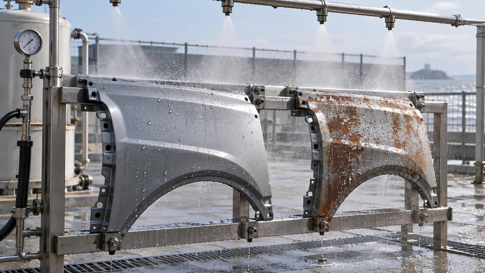
Aluminum can support lightweight panels and offers useful corrosion behavior, but it may need special attention at fasteners and mixed-metal interfaces. Mild or galvanized steel can provide stiffness and cost efficiency. Stainless steel may be justified by moisture, heat, chemical exposure, or appearance. The correct material depends on the environment, load, finish, and quantity.
Finishing is part of the panel specification. Painting, powder coating, plating, conversion coating, anodizing, and passivation affect corrosion protection, electrical contact, appearance, and fit. A coated slot may no longer accept a clip. A masked grounding surface may need a clear boundary. If the panel will experience salt, humidity, heat, or abrasion, the validation plan should represent that condition rather than relying only on a visual inspection.
Prototype the envelope before tooling
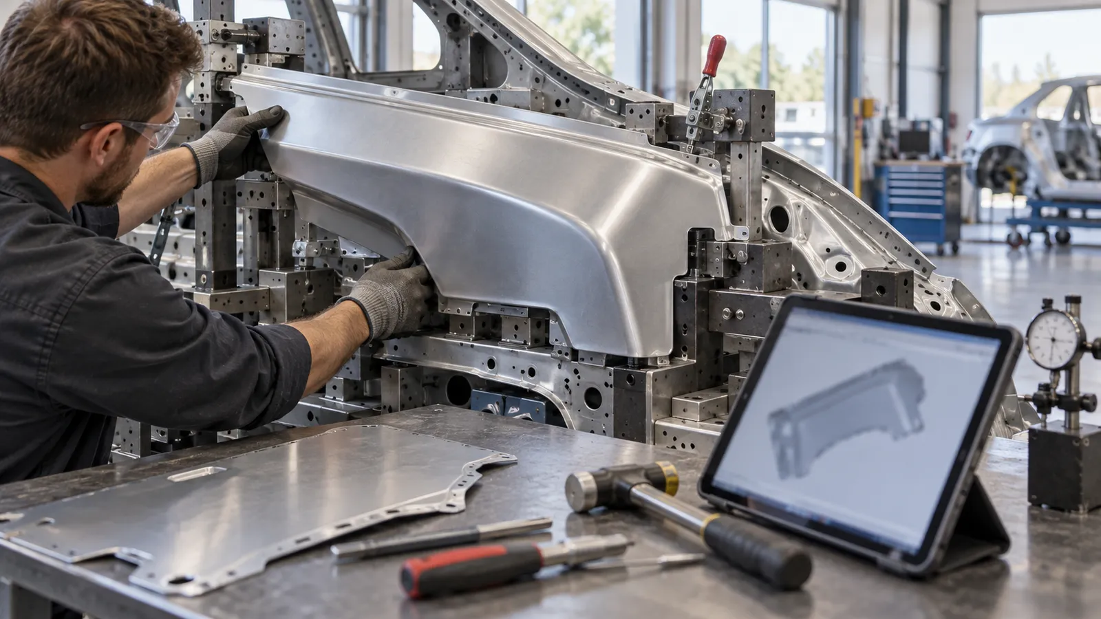
When the vehicle package is still changing, sheet metal fabrication can provide a fast physical check. Laser-cut and bent prototypes are useful for confirming clearance, service access, bracket location, cable routing, and visual proportions. They also give the stamping or production tooling team a physical reference for what the assembly actually needs.
A prototype should be judged against the intended decision. If the purpose is packaging, the material and finish may be simplified. If the purpose is thermal, vibration, corrosion, or grounding validation, the material and joint strategy should be representative. This prevents the team from drawing conclusions from a sample that cannot reproduce the production behavior.
Inspection in the real assembly
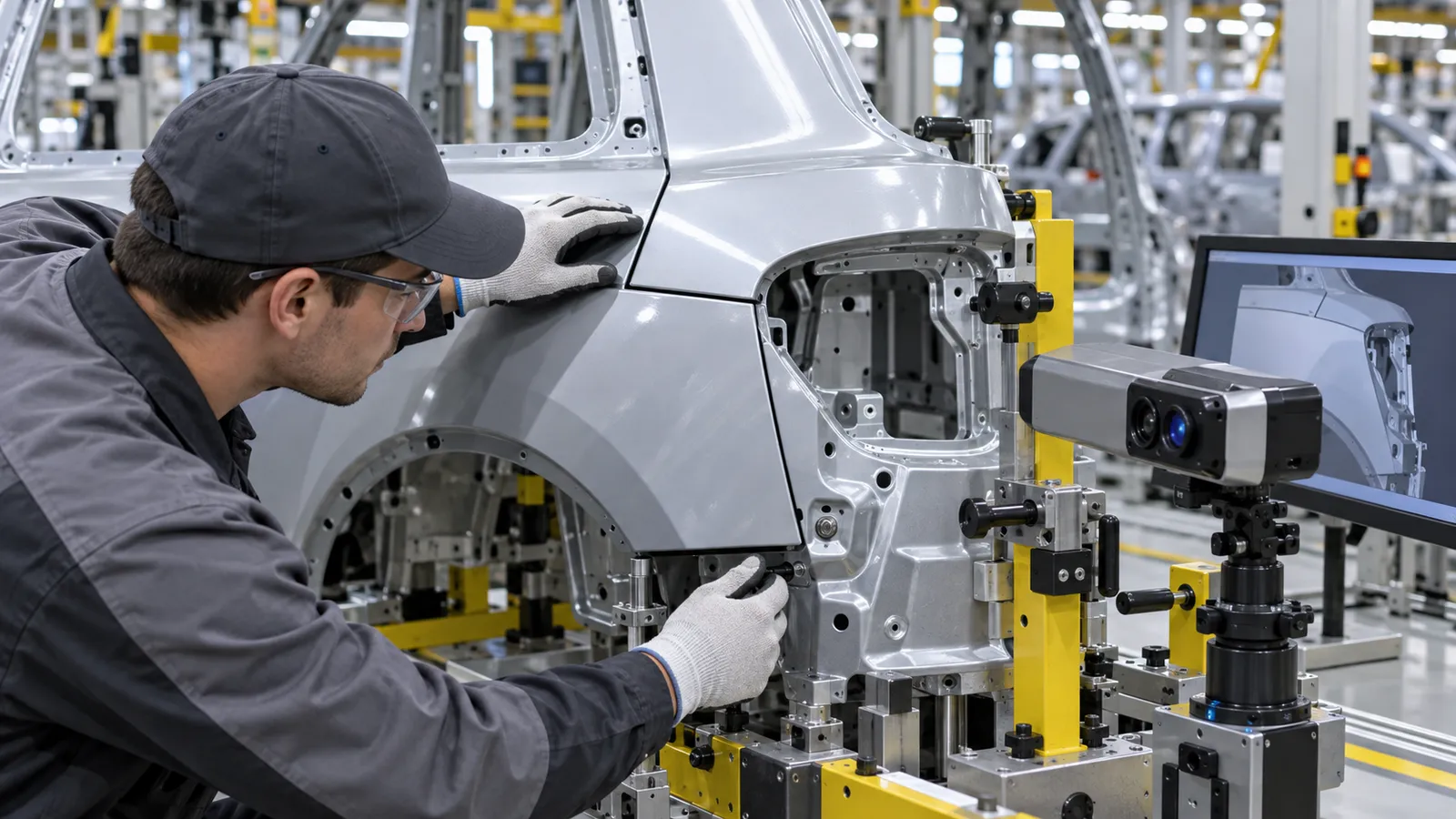
Panel inspection should begin with drawing datums and end with the vehicle envelope. Check profile, hole location, flatness, bend angle, flange position, and surface condition. Then install the panel with the intended fasteners and verify gap, flush, clearance, access, cable protection, sealing contact, and neighboring part movement.
For repeat production, use fixtures and gauges that reflect the functional interfaces. Record which features are critical and which are reference-only. A supplier that coordinates fabrication with CNC machining, finishing, inspection, and assembly can close the loop between a measured part and a usable vehicle component.
Frequently Asked Questions
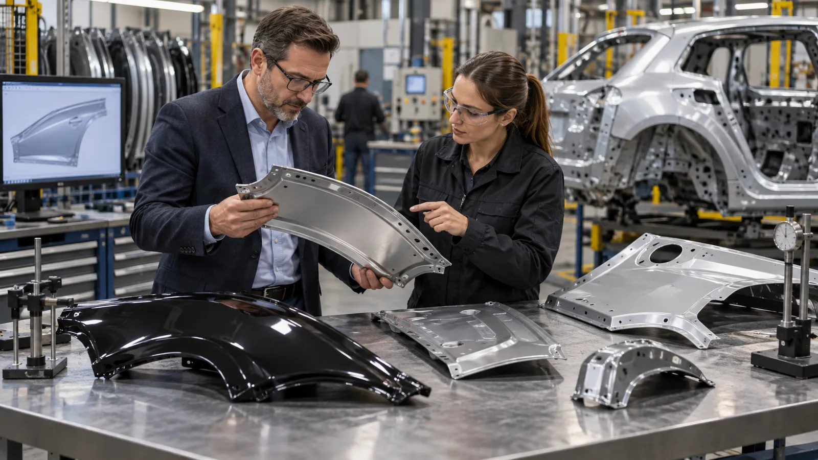
What are automotive sheet metal panels used for?
They are used for body and interior panels, electronics covers, battery shields, heat shields, underbody guards, service panels, and structural or protective enclosures.
How are automotive panels made in low volumes?
Laser cutting, press-brake forming, bending, welding, hardware insertion, and finishing are common flexible routes. The best combination depends on geometry, quantity, appearance, and assembly requirements.
How can panel distortion be controlled?
Use a planned bend and joining sequence, appropriate fixtures, realistic tolerances, controlled weld energy, and inspection after secondary operations. Assembly checks should confirm the final result.
Make the panel serve the complete assembly
A dependable panel is the result of coordinated geometry, material, forming, joining, finishing, inspection, and service access. Treating it as a flat cutout leaves too much risk hidden. Treating it as part of the vehicle architecture produces a component that fits, protects, and can be made repeatedly.

