


Automotive sheet metal parts are not defined only by the material or the cutting method. Their success depends on how the part carries load, locates a neighboring component, survives vibration, and remains economical to produce. A bracket, shield, tray, cover, or structural panel may begin as flat stock, but its final performance is controlled by bend sequence, datum strategy, joining method, finish, and assembly access.
Start with the function, not the flat pattern
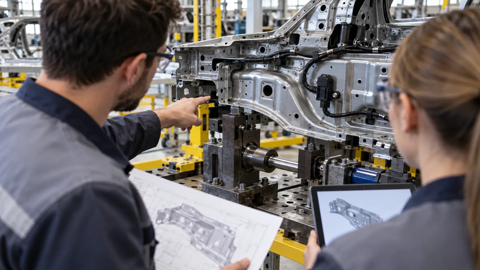
In vehicle programs, the first question is rarely “Can this sheet be cut?” The more useful question is “What must this part continue to do after installation?” A component may hold a sensor at a repeatable position, protect wiring from heat and debris, guide an airflow path, carry a cable load, or prevent two assemblies from contacting each other. Each function creates different requirements for stiffness, edge treatment, hole position, bend accuracy, coating, and inspection.
This is why a supplier should review the surrounding assembly before quoting. A thin shield with generous clearance may be a straightforward fabricated part. The same thickness used beside a high-vibration motor may require beads, ribs, captive hardware, or a different alloy. Treating both parts as interchangeable “automotive sheet metal parts” creates a drawing that looks complete but leaves the performance requirement undefined.
A practical definition should identify the load direction, the supported mass, the temperature zone, the expected vibration, and the interfaces that cannot move. Those facts guide the process choice more effectively than a generic request for laser cutting.
The automotive part families that suit sheet metal
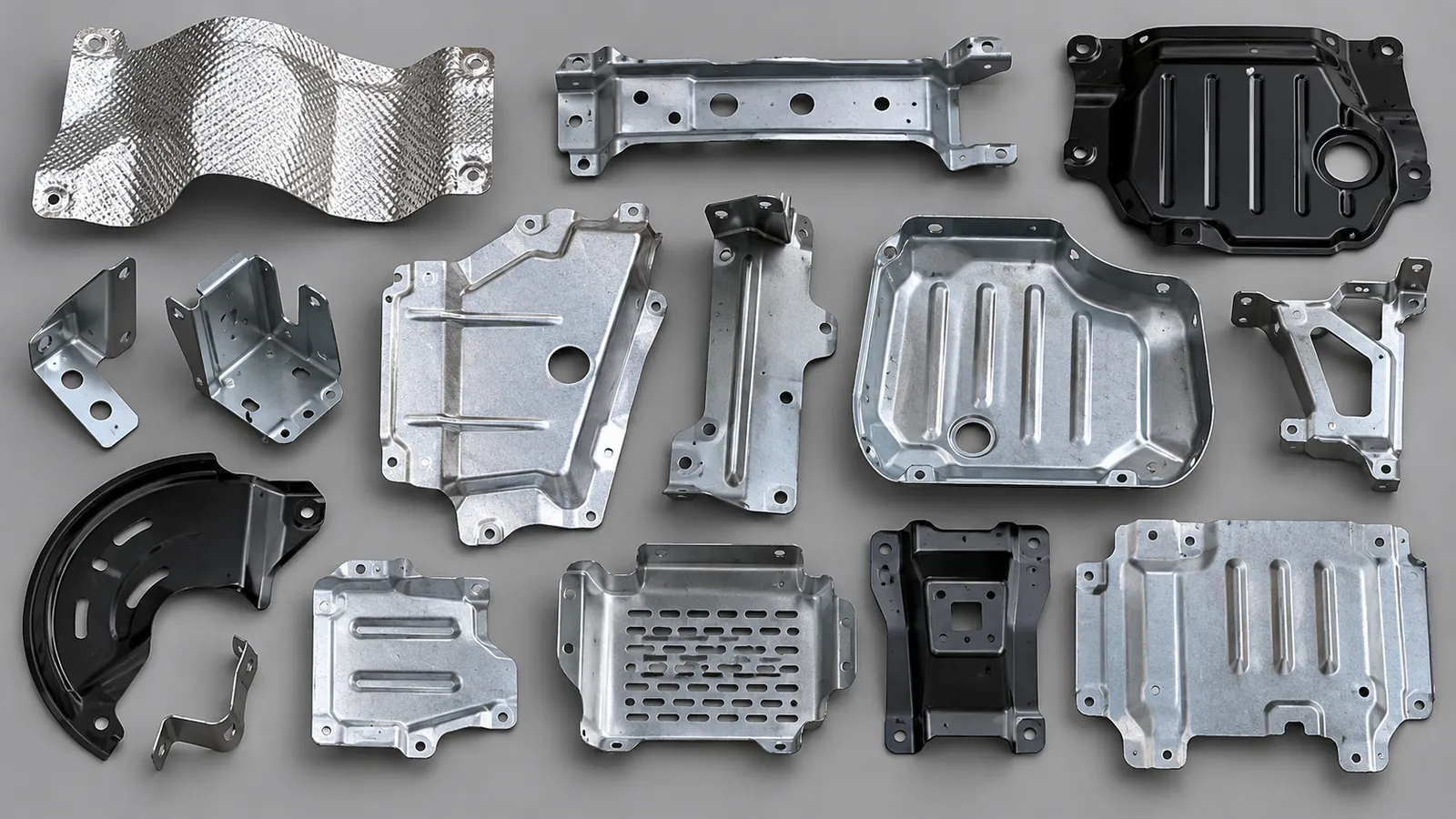
Sheet metal is especially useful when a vehicle component needs a thin, stiff, repeatable shape without the investment required for a deep mold or a large casting die. Common families include mounting brackets, battery and electronics covers, heat shields, sensor guards, cable trays, air-management panels, seat and interior supports, and prototype body or chassis panels.
| Part family | Typical job | Key design concern |
|---|---|---|
| Mounting brackets | Locate and support a component | Hole position, stiffness, and tool access |
| Electronics enclosures | Protect control hardware | Sealing, grounding, heat, and service access |
| Heat shields | Separate hot and sensitive zones | Clearance, thermal exposure, and fastener retention |
| Cable trays and guards | Manage routing and abrasion | Edge safety, bend radius, and assembly sequence |
| Prototype panels | Evaluate fit and appearance | Surface condition, repeatability, and revision speed |
The same part family can be made by more than one route. A low-volume bracket may be laser cut and press-brake formed. A high-volume bracket with a stable geometry may justify progressive stamping. A welded enclosure may combine cut blanks, formed walls, and machined interfaces. The correct choice comes from the part’s function and program stage rather than from a process label chosen in isolation.
Geometry is the real manufacturing specification
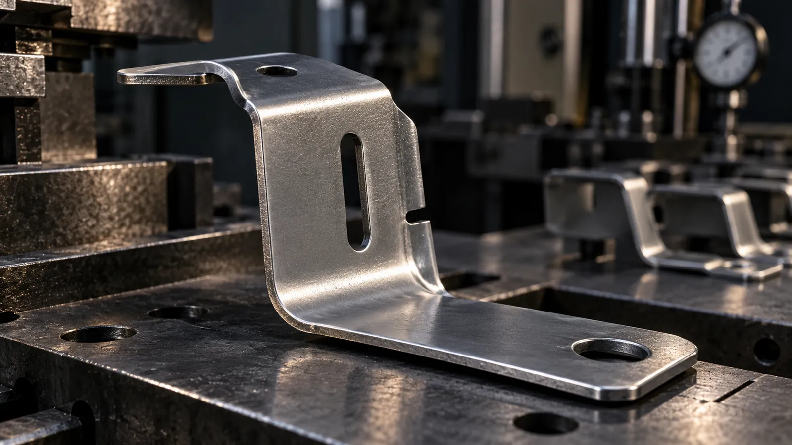
Flat patterns are only the beginning. Bend radius, bend direction, hole-to-bend distance, corner relief, flange width, and material springback determine whether the formed part will match the digital model. Small changes in these details can shift an interface enough to create installation force or misalign a sensor.
Designers should separate critical features from forgiving ones. A mounting hole that establishes a vehicle datum deserves a tighter positional requirement than a clearance slot used only for cable passage. Likewise, a visible outer edge may need a controlled corner and deburr requirement, while an internal edge hidden behind a cover may use a different treatment. This hierarchy keeps the specification meaningful and prevents unnecessary cost.
For complex geometries, a prototype can expose issues that a flat-pattern review will miss. A formed sample can reveal tool interference, bend order problems, insufficient flange width, and poor access for a nut driver. When the part is part of a larger module, checking it in the real envelope is more valuable than inspecting the isolated component on a table.
Choose material around exposure and load
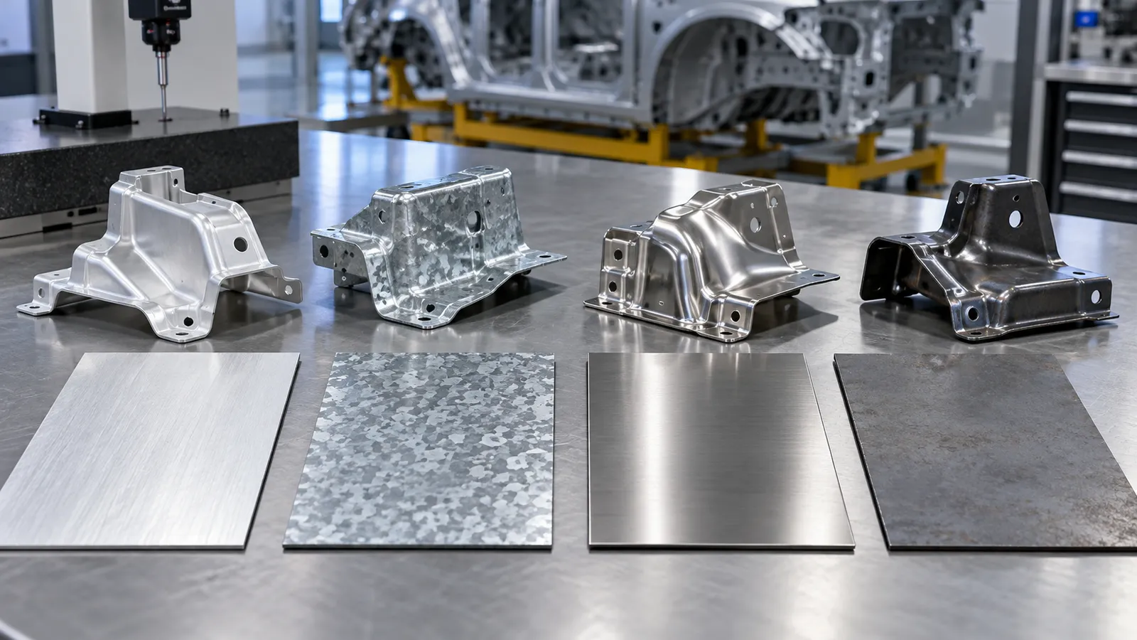
Automotive sheet metal parts may use aluminum, mild steel, stainless steel, galvanized stock, or other engineering grades depending on the environment. Aluminum can reduce mass and offers useful corrosion behavior, but the design must account for local deformation, thread strategy, and galvanic contact with neighboring metals. Carbon steel can provide stiffness and cost efficiency, while stainless steel may be justified by heat, moisture, chemical exposure, or appearance.
Material selection should also include the final finish. Powder coating, plating, conversion coating, anodizing, painting, and passivation each affect corrosion resistance, appearance, electrical behavior, and dimensional build-up. A hole or sliding interface that works before coating may become tight afterward. The drawing should identify which surfaces are functional and which are cosmetic before the finishing route is chosen.
For first builds, it is useful to compare the proposed material with the test plan. If the prototype will only verify packaging, a rapid material substitute may be reasonable. If it will undergo vibration, thermal cycling, corrosion, or electrical grounding tests, the material and finish should represent the intended production condition closely enough to make the result useful.
Select the route from quantity and evidence
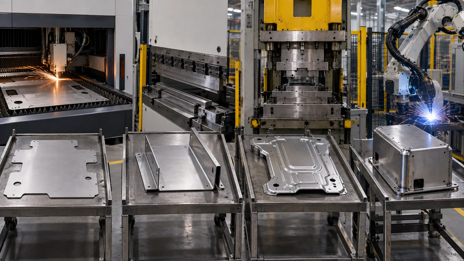
There is no universal best process for automotive sheet metal parts. Laser cutting and press-brake forming are flexible for prototypes and low-volume builds. Stamping becomes more attractive as quantity rises and the geometry stabilizes. Welding, riveting, clinching, and threaded hardware can turn separate formed pieces into a functional enclosure or subassembly.
A good manufacturing plan may deliberately use more than one route. A development bracket can be cut and bent quickly, then redesigned for stamping after the interfaces and loads are confirmed. A sheet metal electronics cover may be fabricated for early packaging tests and later combined with die casting or injection molding for the production version. This staged approach reduces the risk of paying for production tooling before the design has earned it.
For global automotive programs, the quotation should show which operations are included: cutting, forming, deburring, welding, hardware insertion, machining, surface finishing, inspection, packaging, and assembly. Clear operation boundaries make supplier comparisons more useful and expose hidden handoffs.
Quality is an assembly question
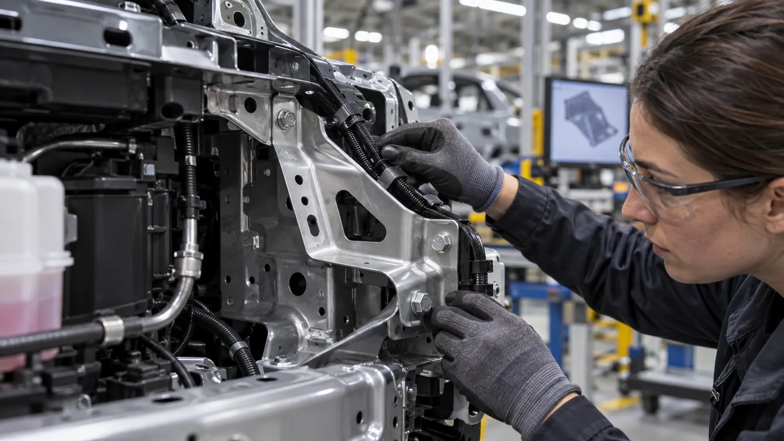
Dimensional inspection is necessary, but an automotive sheet metal part can pass isolated measurements and still fail in the vehicle. A bracket may meet hole coordinates but force a harness against a neighboring edge. A cover may match its external dimensions but prevent service access. A shield may be flat enough on a table yet resonate after it is fastened to the vehicle structure.
Quality planning should therefore connect drawing datums to the actual assembly sequence. First-article checks can verify critical hole locations, bend angles, flatness, and finish. Fixture checks can confirm fit, clearance, fastener access, and repeatable location. When the application is sensitive to vibration, heat, or corrosion, the validation plan should include the relevant environment rather than relying only on room-temperature dimensional results.
What a useful RFQ should reveal
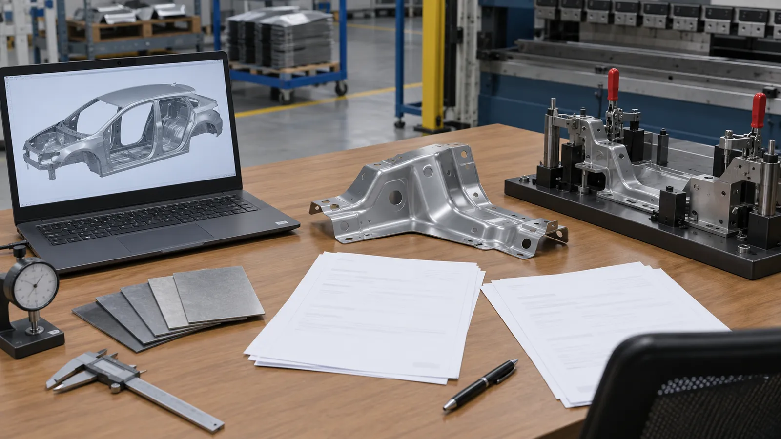
A strong RFQ for automotive sheet metal parts gives the supplier enough information to separate engineering risk from simple fabrication effort. Include the 3D model and drawing, material and thickness, annual or pilot quantity, required finish, critical datums, joining method, inspection expectations, and the assembly context. Mark cosmetic surfaces and functional interfaces separately.
It is also helpful to state what is still open. If the part is being designed around a test, say which dimensions are provisional. If the production route may change from fabrication to stamping, ask for feedback on the transition. A supplier that can combine sheet metal fabrication with CNC machining, surface finishing, inspection, and prototype-to-production support can then recommend a route rather than quote a single operation blindly.
Frequently Asked Questions
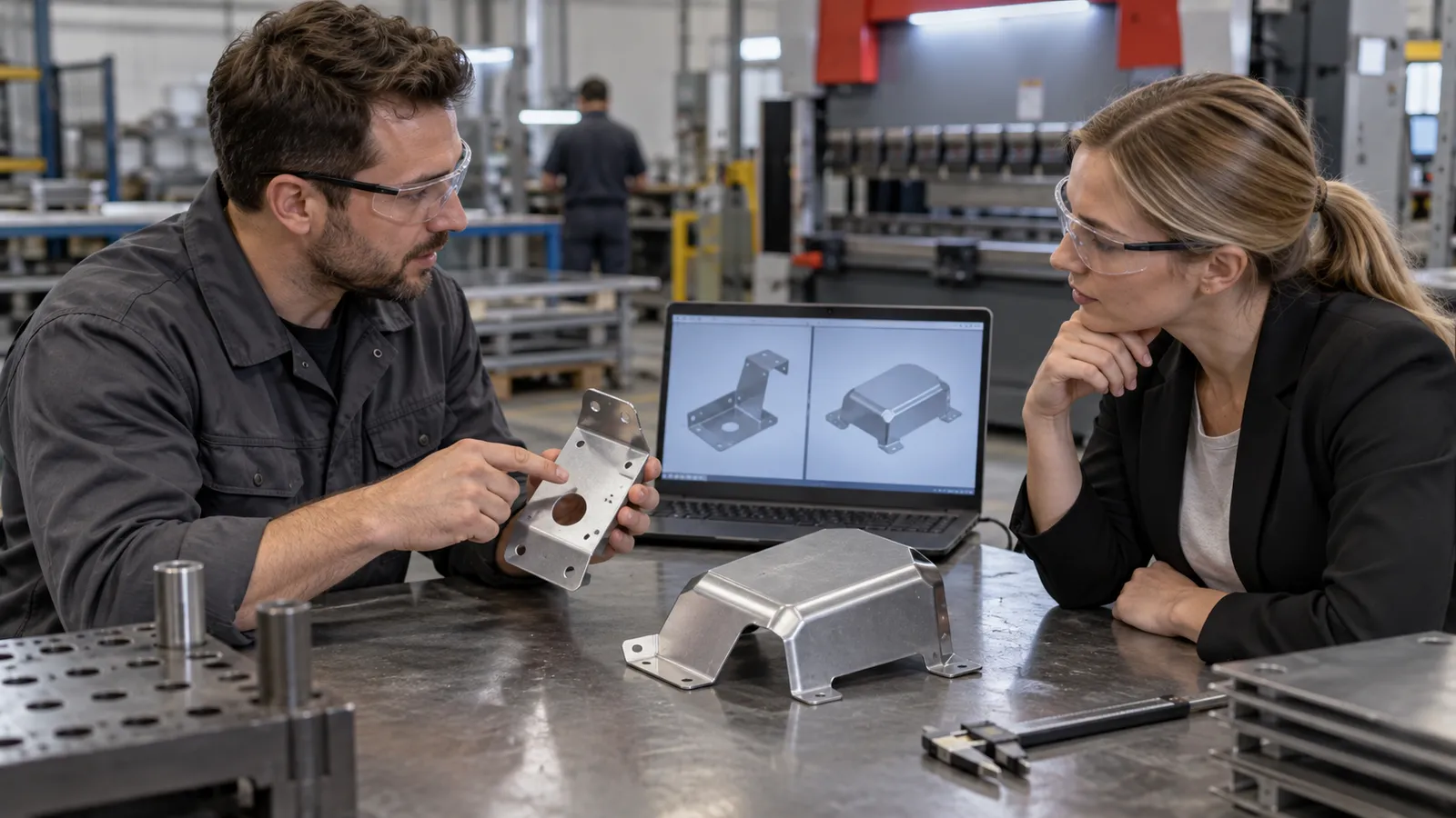
What are common automotive sheet metal parts?
Common examples include brackets, heat shields, electronics covers, cable trays, sensor guards, structural supports, and prototype panels. The right process depends on the part’s load, exposure, geometry, quantity, and assembly interfaces.
Is laser cutting enough for an automotive sheet metal part?
Laser cutting produces the blank, but many vehicle parts also require forming, deburring, welding, hardware insertion, machining, or surface finishing. The complete route should be evaluated against the finished assembly.
When should stamping replace fabricated sheet metal?
Stamping becomes more attractive when the geometry is stable and production volume justifies dedicated tooling. Fabrication is often more flexible for prototypes, design changes, and lower-volume programs.
Build the part around the vehicle decision
The strongest sheet metal programs connect design intent, material behavior, process capability, inspection, and assembly evidence. That connection is what turns a flat blank into a dependable vehicle component. For teams comparing routes, Jucheng Precision can coordinate sheet metal fabrication with CNC machining, molding, 3D printing, finishing, and inspection so the prototype or low-volume build reflects the real manufacturing decision.

