


When stamping is the right answer
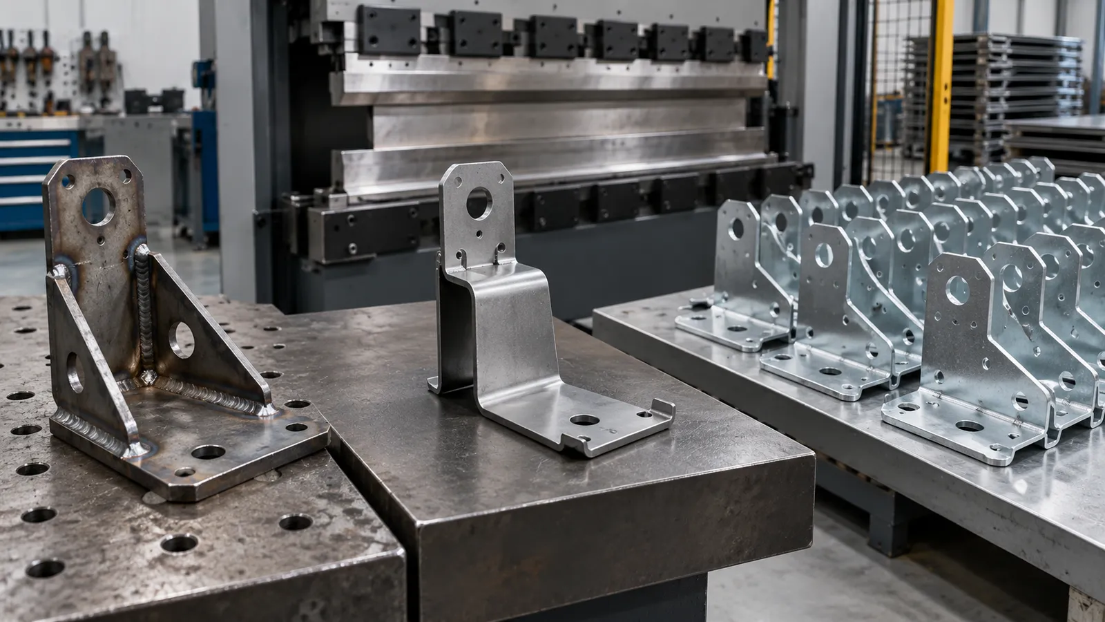
Stamping should be considered after the part’s interfaces and loads are understood, not as the automatic first step. For an early design with uncertain holes, bend positions, or packaging, laser cutting and press-brake forming can preserve flexibility. Once the design stops changing and the program needs repeated parts, a dedicated tool can reduce handling, shorten cycle time, and make feature location more consistent.
The decision is also shaped by part size and geometry. A simple reinforcement with a few bends may be a good progressive-stamping candidate. A deeper panel may need draw operations, controlled radii, and careful material flow. A small clip may be inexpensive to stamp but difficult to inspect if the drawing does not define the functional spring position. In each case, the process must be selected around the finished use.
What the die must accomplish
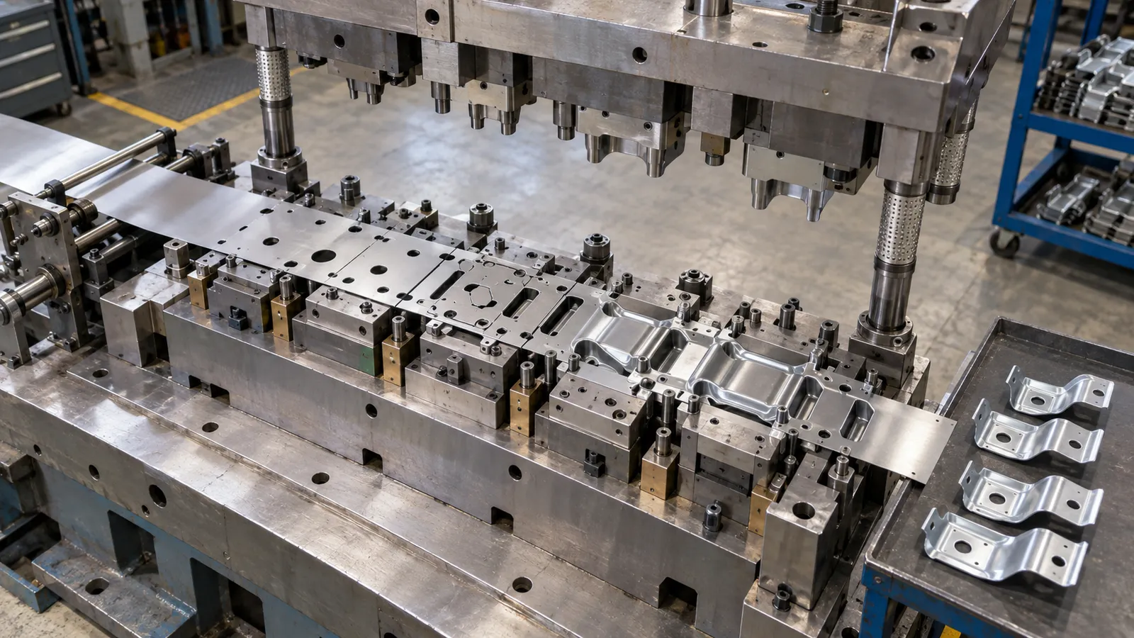
A stamping die is a controlled mechanical system, not just a negative shape. It must guide the stock, locate each operation, manage material flow, maintain the intended clearance, and release the part without damaging edges or form features. A progressive die may combine piercing, forming, embossing, trimming, and cutoff. A transfer or single-operation tool may be more appropriate when the part needs larger movement or a different sequence.
| Tool decision | Why it matters | What the drawing should clarify |
|---|---|---|
| Progressive or transfer | Controls handling and operation sequence | Strip layout, carriers, and part orientation |
| Forming radius | Influences cracking and springback | Material grade and critical bend geometry |
| Piercing timing | Affects hole accuracy after forming | Whether holes are made before or after bends |
| Trim and cutoff | Controls edge condition and repeatability | Parting edge, burr direction, and deburr need |
Geometry decisions that control reliability
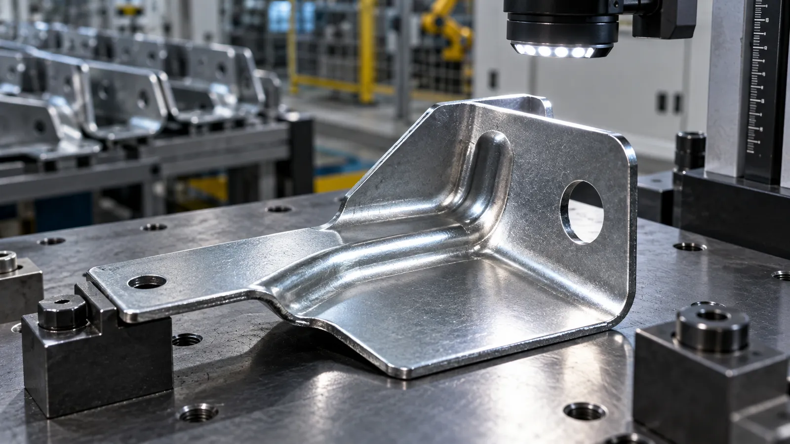
The strongest stamping designs give the material room to move. Tight inside radii, abrupt thickness changes, narrow flanges, and holes too close to a bend can create splits, distortion, or unstable springback. A bead or rib can add stiffness more efficiently than simply increasing thickness, but it must fit the die and remain accessible to inspection.
Hole location deserves special attention. A hole used for a fastener may tolerate a clearance range, while a hole locating a sensor or bushing may establish a vehicle datum. Those features should be identified separately. The supplier can then recommend whether piercing before forming, piercing after forming, or a secondary machining operation gives the most reliable result.
Automotive sheet metal parts often fail at the handoff between the stamping operation and assembly. A flange may be dimensionally correct but block a weld gun. A formed tab may meet the model but prevent a clip from seating. Reviewing the part in its assembly envelope catches these problems before a tool is locked into production.
Material, thickness, and springback
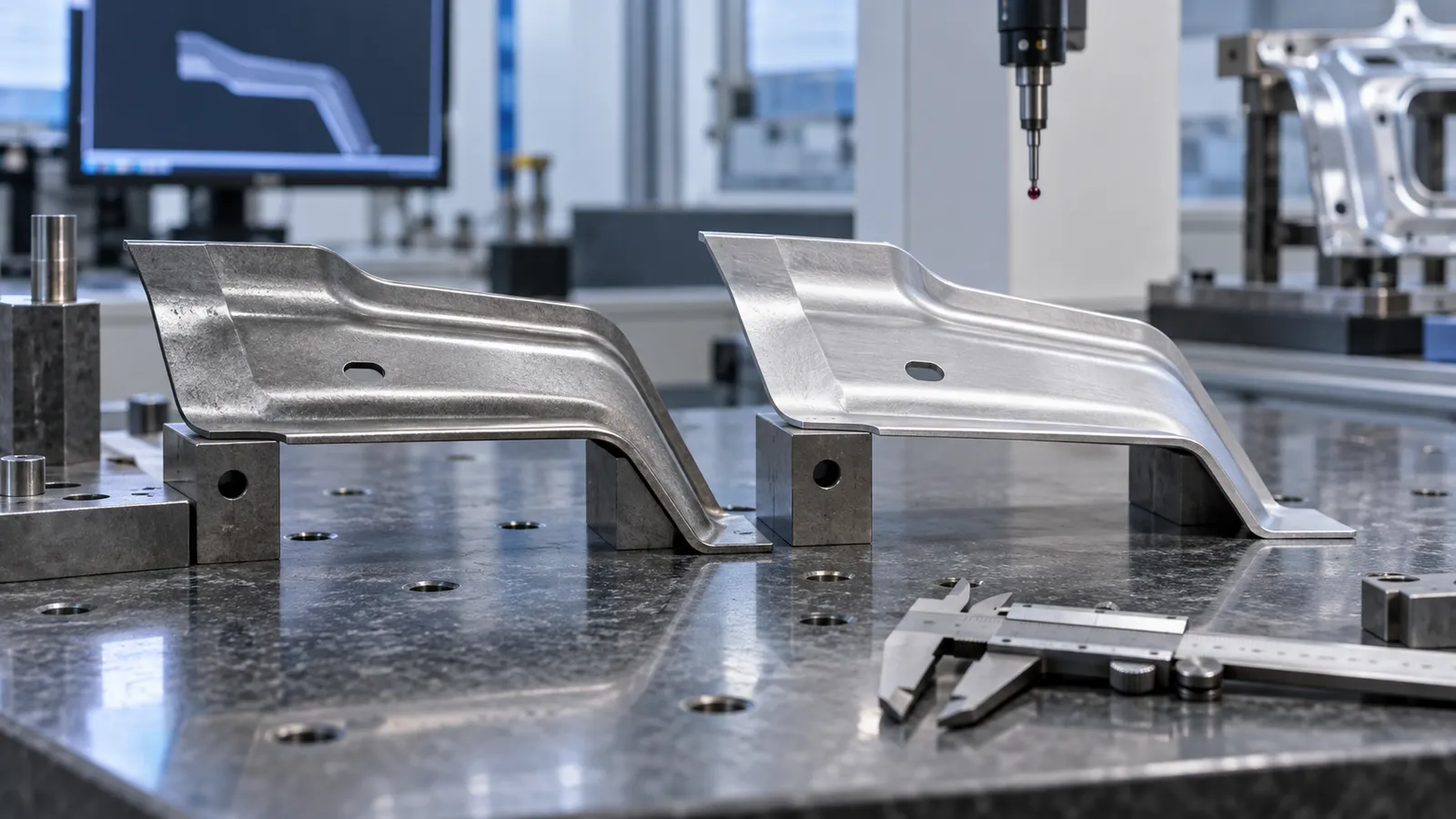
Automotive stamping may use low-carbon steel, galvanized steel, stainless steel, aluminum alloys, or other grades chosen for stiffness, corrosion behavior, weight, and cost. The same nominal thickness does not behave the same across materials. Yield strength, elongation, temper, rolling direction, and coating can change the forming window.
Springback is a design and process issue rather than a final inspection surprise. Compensation in the die, controlled forming radii, consistent material supply, and realistic tolerance allocation work together. If a component will receive paint, powder coating, plating, or another finish, the dimensional build-up and contact surfaces should be considered from the beginning.
For prototypes, a fabricated sample can be valuable even when the production route will be stamping. It verifies the surrounding interfaces, gives the tool designer real assembly evidence, and reduces the chance that the first stamped parts become an expensive packaging experiment.
From blanking to finished part
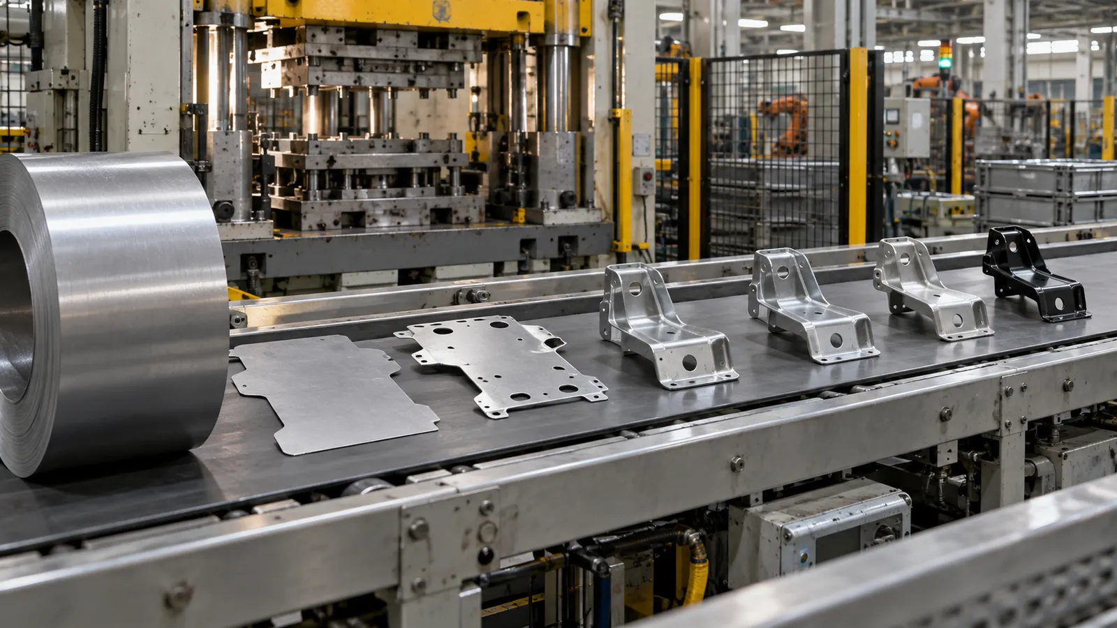
A robust process plan describes the whole route: material receipt, blank preparation, forming, piercing, trimming, deburring, hardware insertion, welding if required, surface finishing, inspection, and packaging. A part may leave the press in good condition but change during welding or coating. Those downstream operations belong in the quality conversation.
- Review the model and drawing. Confirm datums, material, thickness, bend intent, and cosmetic surfaces.
- Run a manufacturability study. Check strip layout, forming sequence, tool access, material flow, and likely failure modes.
- Validate the first-off parts. Measure critical features and test the part in the surrounding assembly.
- Stabilize the process. Track variation, tool wear, burr direction, and finish condition as volume increases.
This staged approach is useful when a supplier provides more than press capacity. Combining stamping or fabrication with CNC machining, finishing, inspection, and assembly support helps keep the final component aligned with its vehicle-level purpose.
How repeatability is verified
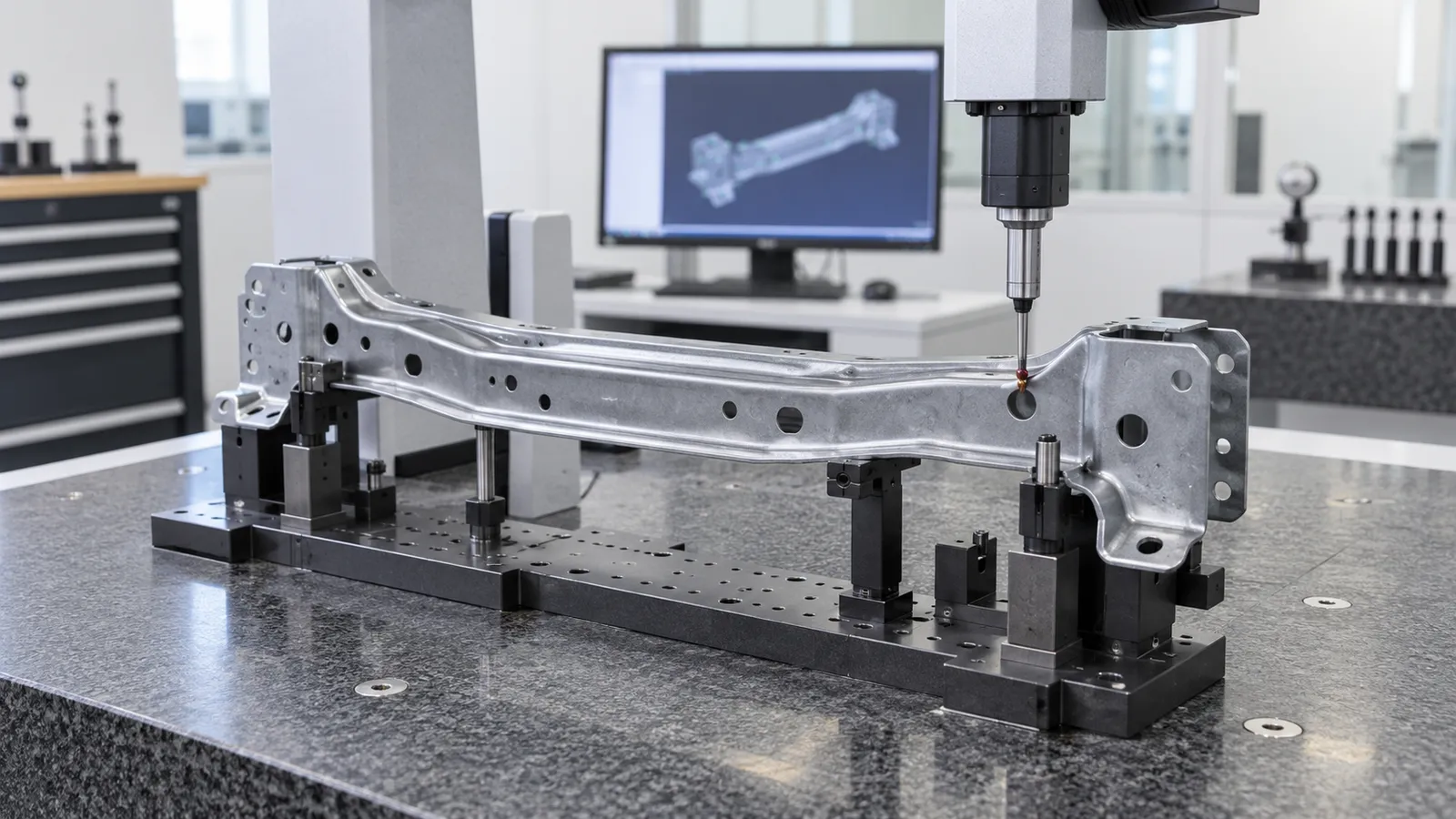
Inspection should mirror the way the part is used. A coordinate check can confirm hole position, bend location, flatness, and profile. A fixture check can confirm that the bracket locates correctly, that the fastener tool reaches the joint, and that the finished part does not interfere with wiring or adjacent panels. For safety-relevant or vibration-sensitive parts, functional testing may matter more than a long list of non-critical dimensions.
Control plans should identify the features that deserve frequent monitoring. Tool wear can change burrs and hole size. Material lot changes can shift springback. Coating thickness can affect a sliding fit. Recording these relationships gives the production team a way to investigate variation instead of treating every nonconformance as an isolated event.
Questions for an automotive stamping RFQ
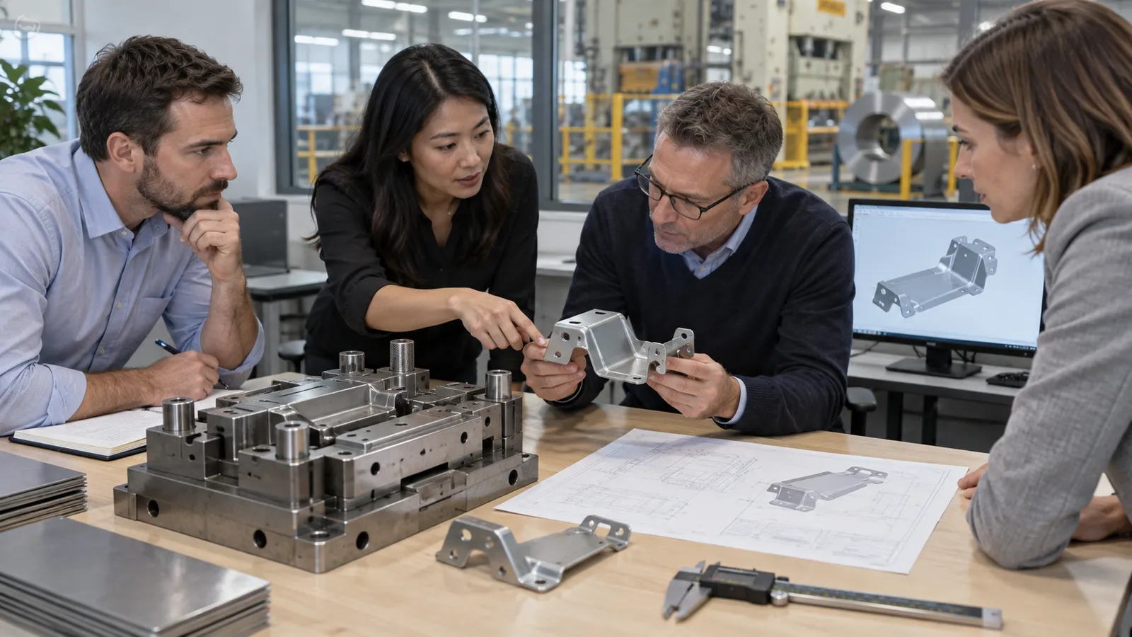
An RFQ should include the 3D model, drawing revision, material and thickness, expected volume, prototype requirement, finish, joining method, inspection level, packaging, and delivery assumptions. Explain which interfaces are fixed and which are still under development. If the program may move from fabricated prototypes to stamped production, ask the supplier to identify the transition risks and likely tooling approach.
It is also useful to request a clear separation between tooling, part price, secondary operations, inspection, and engineering changes. That structure allows a buyer to compare the economics of stamping with fabrication or machining on the same functional basis.
Frequently Asked Questions

What are common automotive metal stamping parts?
Common examples include brackets, reinforcements, clips, shields, battery supports, seat components, and structural panels. The suitable die type depends on geometry, material, quantity, and the required feature sequence.
Are stamped parts better than laser-cut and bent parts?
Neither route is universally better. Fabrication usually offers faster design changes and lower tooling commitment. Stamping often offers stronger repeatability and lower piece cost after the geometry and volume justify a dedicated tool.
Can stamped automotive parts receive secondary machining?
Yes. Critical bores, threads, datum surfaces, or special holes may be machined after forming when the stamping operation alone cannot hold the required interface condition.
Use the tool to protect the program decision
A stamping tool earns its place when it improves repeatability without hiding unresolved design risk. The best results come from linking material behavior, die sequence, inspection, finishing, and assembly evidence. That is the difference between ordering stamped blanks and developing dependable automotive components.

