


Successful product scaling relies heavily on identifying manufacturing limitations during the earliest stages of hardware design. Applying comprehensive design for manufacturability DFM prototyping practices protects engineering budgets by preventing geometries that are physically impossible to mold or machine. Many hardware startups experience severe developmental delays because they fabricate complex assemblies that function as 3D prints but violate basic physics in high-volume environments. Introducing robust design reviews early ensures physical mockups translate seamlessly into commercial steel tooling.
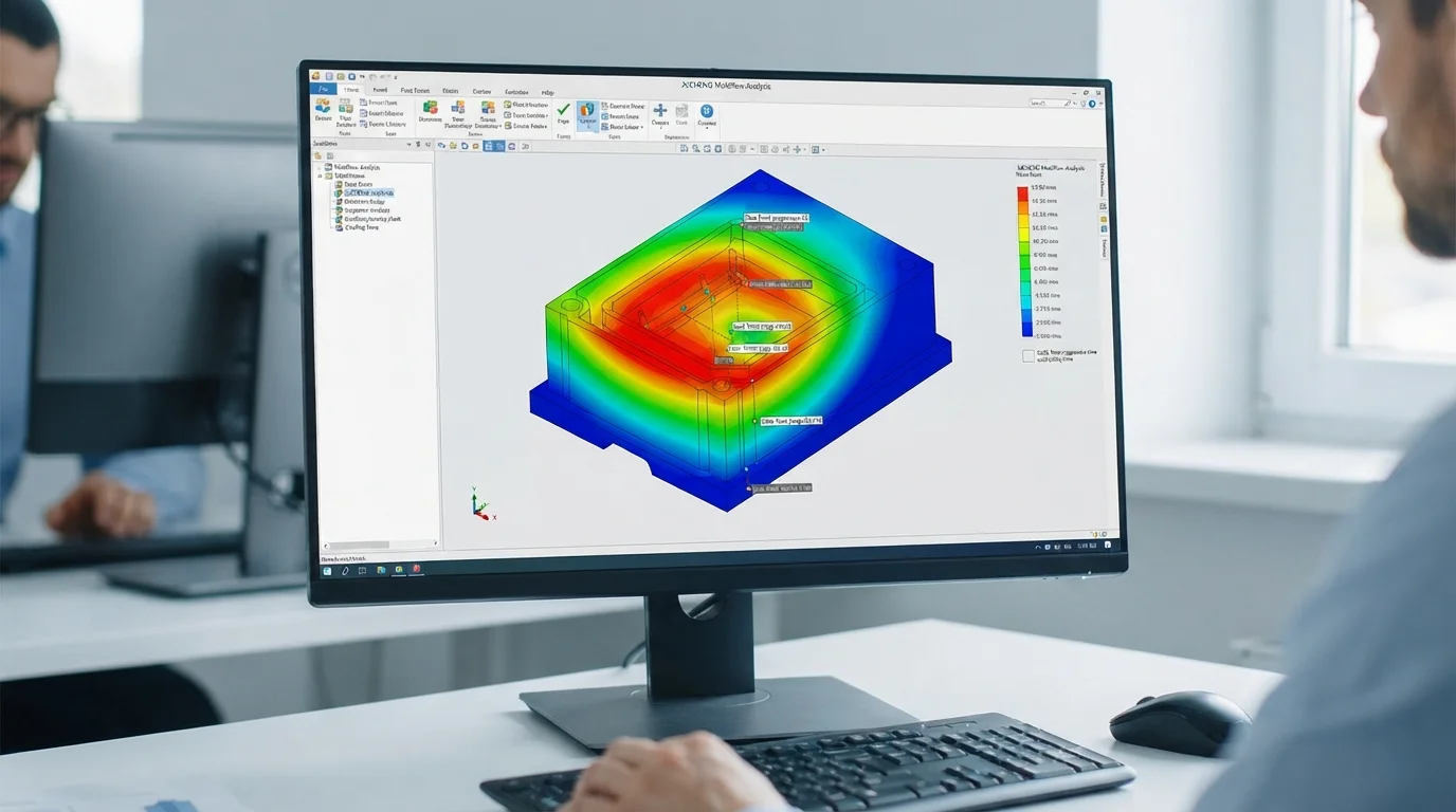
Sourcing expert engineering reviews before cutting tool steel eliminates high financial risks associated with post-mold modification reworks. Manufacturing specialists evaluate parting lines, gate positions, draft angles, and wall uniformity using dynamic CAD simulation software. Resolving material shrinkage and warpage risks during functional validation cycles ensures part clearances remain highly repeatable. Mechanical design groups secure pristine surface finishes and optimal mechanical strength by addressing structural limitations early.
Table of Contents
1. Molding Physical Limitations and Prototyping DFM Value
2. Simplifying Geometries to Avoid Expensive Custom Tooling
3. Standardizing Radii, Wall Thickness, and Tolerance Clearances
Molding Physical Limitations and Prototyping DFM Value
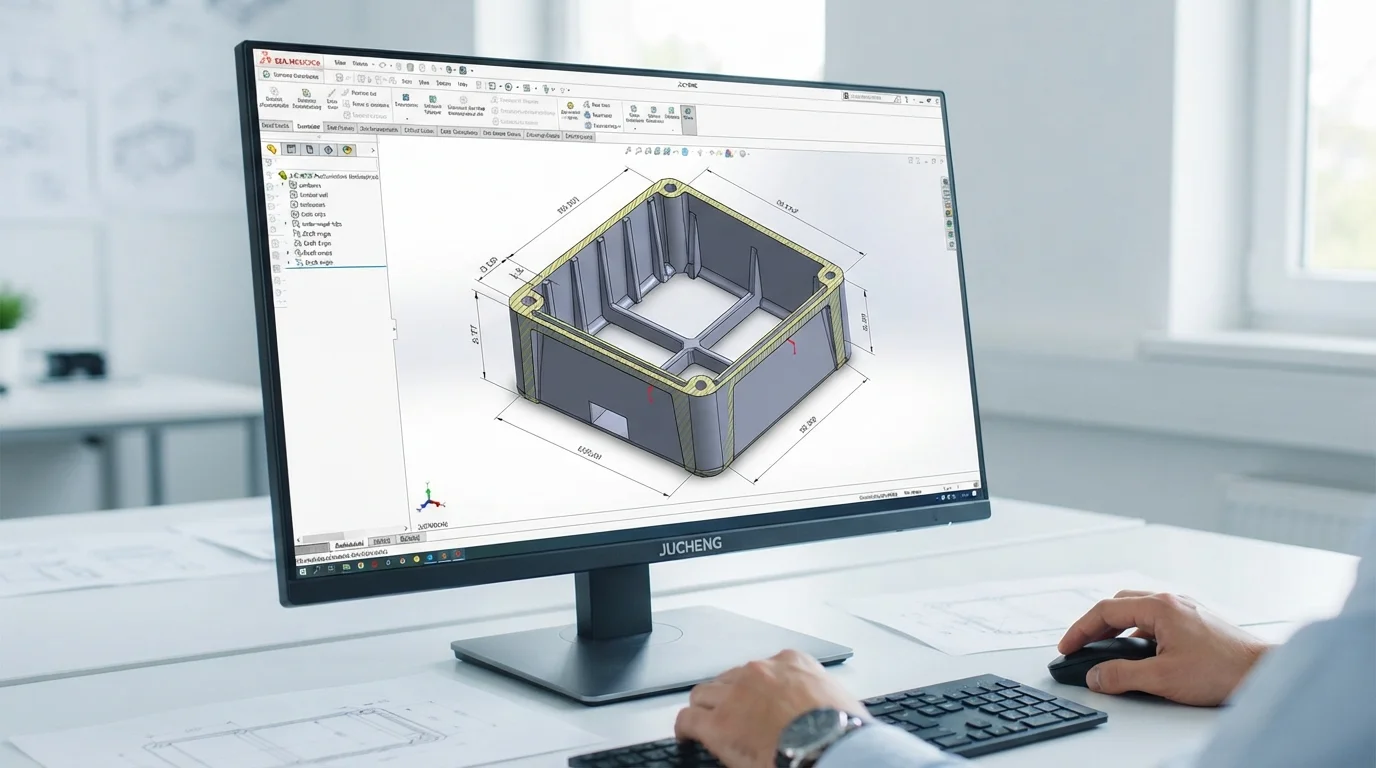
Question: Why should DFM principles be applied during the prototyping phase? Early integration prevents structural features that require complex sliding mold mechanisms or cause injection-molding sink marks.
Developing highly intricate parts utilizing 3D printing provides immense design freedom, yet additive machines bypass critical physical constraints of molding. Features like deep internal undercuts, zero-draft walls, and variable thickness ribs print effortlessly but fail instantly when transitioning to steel tools. Failing to recognize these constraints during early development creates a false sense of security that leads to catastrophic design failures. Structural designers must respect physical manufacturing boundaries to ensure their physical mockups remain highly scalable.
Implementing thorough design for manufacturability DFM prototyping sweeps allows mechatronics groups to identify thick plastic sections that cause cosmetic sink marks. Adjusting part geometries to incorporate uniform walls ensures even polymer cooling during volume injection runs. Sourcing early technical reviews establishes a clear, risk-free pathway toward mass production from the very first physical sample.
Simplifying Geometries to Avoid Expensive Custom Tooling
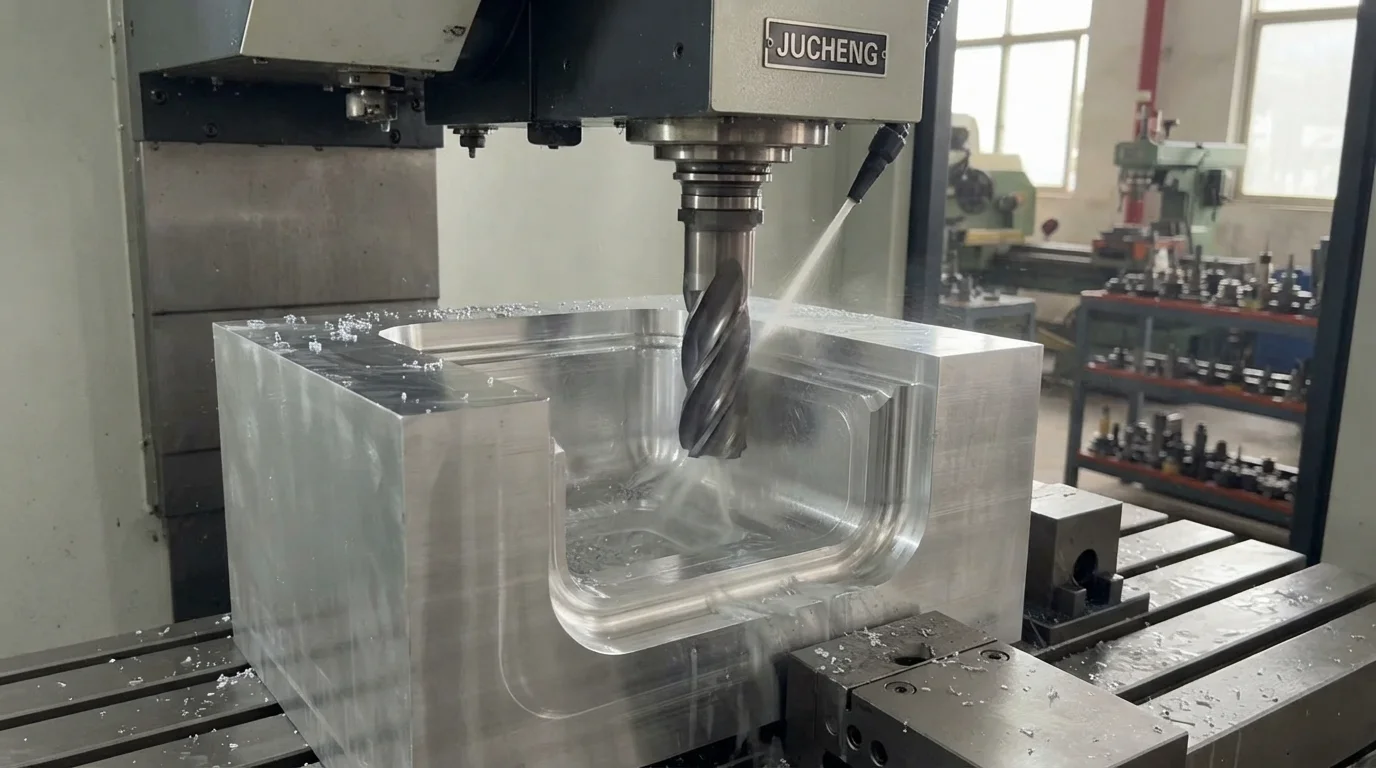
Question: How are tooling costs reduced during development? Eliminating complex undercuts and integrating uniform draft angles avoids the need for expensive mechanical slide cores.
Intricate internal undercuts and interlocking features require complex mechanical sliders or lifters inside injection molds, increasing tooling expenditures dramatically. Product developers utilize strategic rapid prototyping design techniques to eliminate these undercuts by implementing simple sliding shut-offs. Designing simple split lines allows mold halves to open and close along a single axis, reducing overall mold complexity. Simplifying core features lowers initial capital requirements and accelerates tooling lead times.
Draft angles represent another critical geometric parameter that directly influences part ejection safety and surface cosmetic finishes. Vertical walls without adequate draft can drag against core steel, creating visible scuff marks and stress cracks during ejection. Incorporating a minimum draft angle of 1.5 degrees on all vertical features allows molded plastic to slide free easily. Specialized textured finishes may demand up to 3 degrees of draft to prevent dragging against the mold cavities.
Optimizing internal fillet radii also simplifies multi-axis CNC machining by eliminating deep, sharp corners that require specialized micro-cutters. Generous radius values allow standard endmills to cut profiles quickly without tool vibration or deflection. Mechanical designers lower manufacturing expenses by designing parts that fit standard cutting tool diameters.
Standardizing Radii, Wall Thickness, and Tolerance Clearances
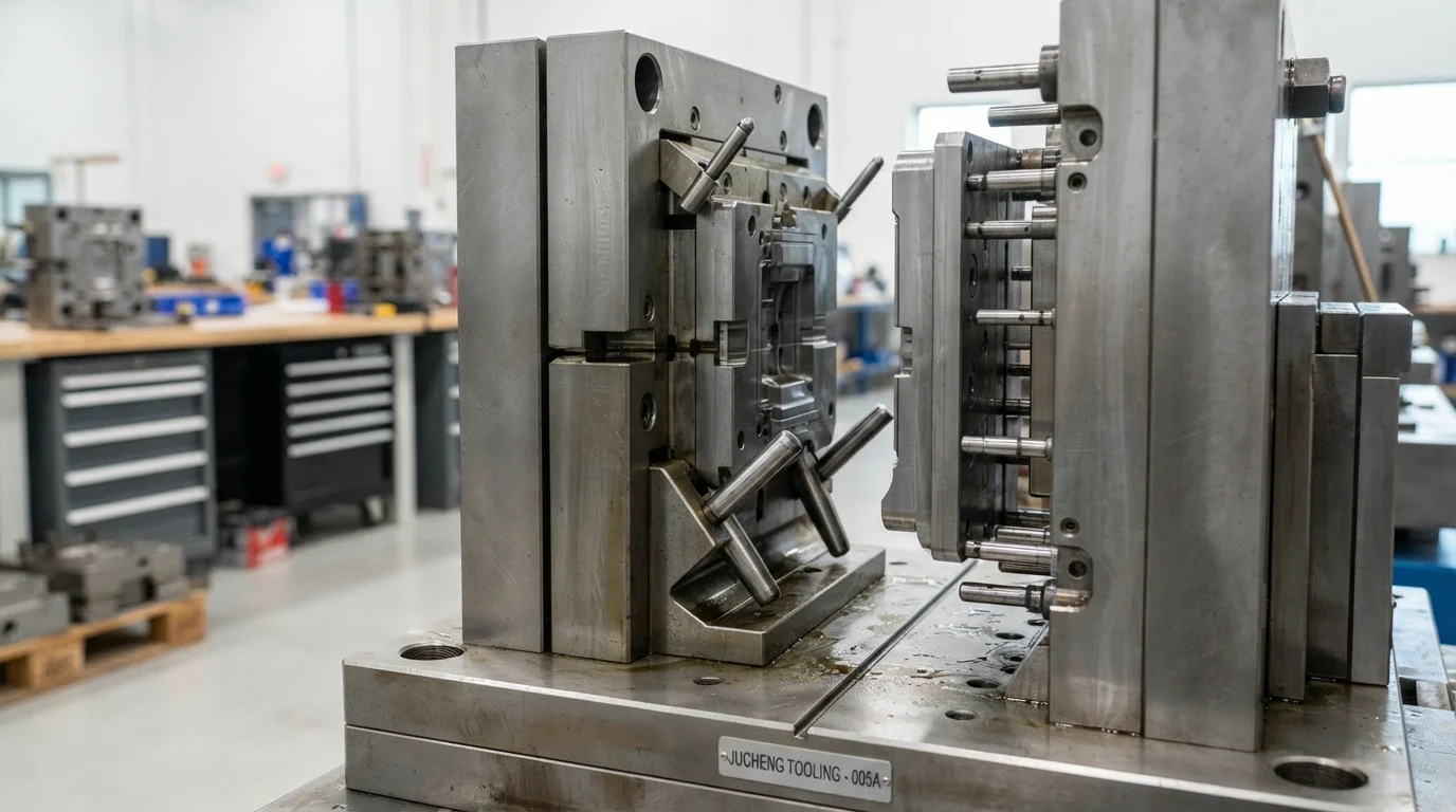
Question: What is the primary cause of warpage in plastic injection molded parts? Non-uniform wall thickness causes uneven cooling rates, resulting in high internal stresses and post-mold twisting.
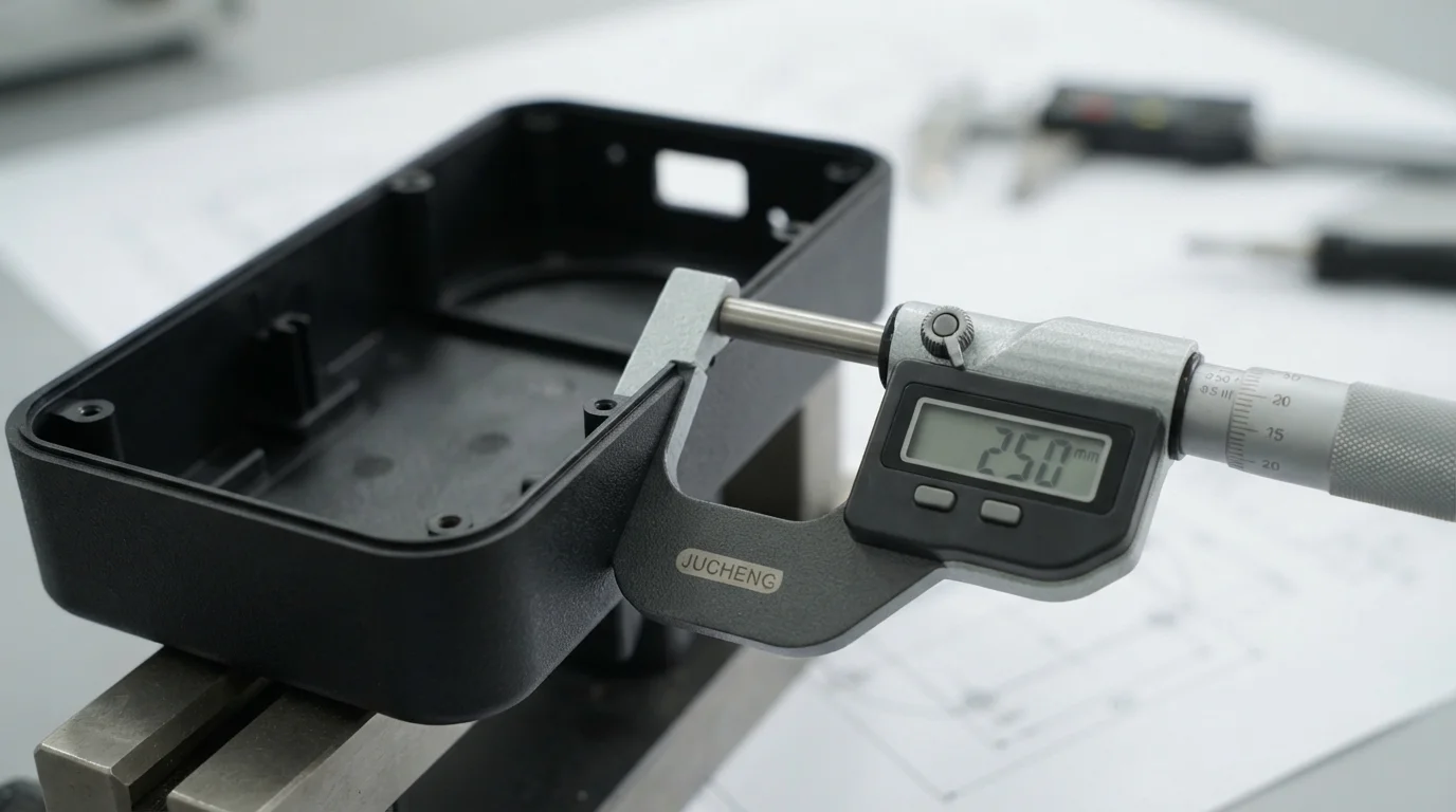
Maintaining uniform wall thickness represents the golden rule of plastic part engineering, preventing uneven volumetric shrinkage and cosmetic splay. Thick plastic hubs or solid bosses must be cored out and supported by thin reinforcing ribs to ensure consistent polymer solidification. Rib thicknesses are generally restricted to 60 percent of the nominal wall to avoid visible sink marks on the opposite show face. Sourcing early dimensional validation ensures interlocking features align perfectly under physical dynamic loads.
Adhering to strict design for manufacturability DFM prototyping guidelines ensures that target dimensional tolerances remain realistic across different manufacturing processes. Tight tolerance expectations must be balanced carefully against physical material capabilities to avoid unnecessary machining setups. This technical comparison table outlines baseline design parameters for CNC machining versus plastic injection molding:
| Manufacturing Parameter | CNC Machining Guideline | Injection Molding Guideline | Primary Engineering Reason |
|---|---|---|---|
| Minimum Wall Thickness | 0.8 mm (metals), 1.5 mm (plastics) | 1.2 mm to 3.0 mm | Prevent part deflection, ensure proper mold flow |
| Recommended Draft Angle | Zero draft permitted | 1.5° to 3.0° minimum | Prevent scuff marks, allow easy part ejection |
| Standard Tolerance | ±0.05 mm to ±0.01 mm | ±0.1 mm to ±0.15 mm | Match process repeatability, reduce tooling costs |
Jucheng Precision operates a fully equipped manufacturing setup containing 150+ CNC machines, including 25 high-precision 5-axis Haas/Mazak machines to mill complex structural linkages. Factory teams deliver comprehensive 24-hour free DFM analyses to resolve draft angles, wall margins, and gating marks before mold core cutting begins. Sourcing high-fidelity pre-production parts prevents tooling reworks and protects launch budgets.
Flexible manufacturing programs with no minimum order requirements allow hardware developers to refine complex components over multiple iterations. Specialized rapid tooling molds deliver high-quality injection-molded components within 4 to 15 days, minimizing the downtime between engineering revisions. Sourcing your prototypes from a certified manufacturer ensures your designs transition smoothly from early concept models to mass series production.
Frequently Asked Questions (FAQ)
What is the best way to handle deep internal pockets in CNC prototype designs?
Designing generous internal fillet radii allows high-speed milling cutters to clear material efficiently without causing tool deflection or vibration. Deep pockets should be designed with depth-to-width ratios below four to prevent tool breakage.
How do rib features improve structural strength without increasing wall thickness?
Reinforcing ribs provide exceptional load-bearing stiffness while maintaining thin, uniform walls that cool quickly and resist volumetric shrinkage. Designing ribs with a thickness of 60% of the nominal wall prevents visible cosmetic sink marks.
Why are sliding cores expensive in rapid tooling?
Mechanical sliders require precise hand-fit alignments and moving steel components, which increases initial mold fabrication hours and material costs. Designing simple split lines or sliding shut-offs eliminates these extra tooling mechanisms entirely.

