


Translating digital product concepts into physical hardware requires crystal-clear technical communication between the product designer and the tooling machinist. Relying solely on a naked 3D STEP file without accompanying engineering drawings forces manufacturers to guess which linear surfaces require micron-level precision and which areas allow standard commercial breathing room. Learning how to specify tolerances on CAD for rapid tooling eliminates costly manufacturing ambiguity, prevents disastrous assembly misalignments, and ensures your rapid bridge tooling runs smoothly from the first trial shot.
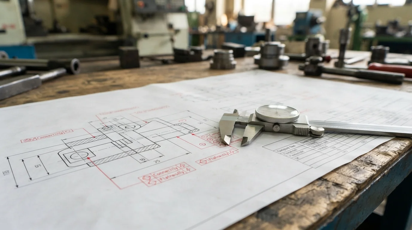
Avoiding expensive over-design demands a firm grasp of geometric dimensioning and tolerancing principles tailored specifically for soft alloy injection molds. Whether your NPI project incorporates high-performance engineering plastics like POM (Acetal) or structural Aluminum enclosures, precise drawing callouts protect your budget. Let us examine essential drafting practices that safeguard your design intent while optimizing machining efficiency.
Table of Contents
1. Best Practices for 3D and 2D Drawing Callouts
2. Avoiding Over-Tolerancing to Save Prototype Budgets
3. Communicating Critical Mating Dimensions to Your Manufacturer
Best Practices for 3D and 2D Drawing Callouts
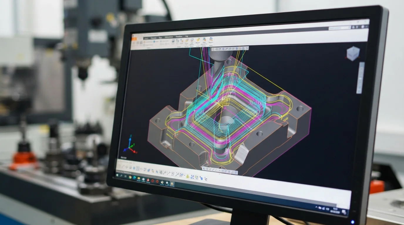
Question: Why is a digital 3D STEP file alone insufficient for manufacturing precision rapid injection molds? A 3D model defines spatial geometry perfectly, but it completely lacks critical manufacturing context such as surface finish callouts, datum reference frames, and specific GD&T geometric controls.
Pairing your 3D digital model with a clearly structured 2D PDF drawing containing GD&T symbols removes ambiguity during toolpath programming. For projects requiring diverse manufacturing routes—such as pairing custom injection-molded covers with auxiliary Sheet Metal chassis brackets—clear drawing annotations ensure every mating interface aligns correctly.
Establishing rigorous documentation standards involves monitoring specific drawing checklist criteria:
| Drawing Element | Engineering Purpose | Impact on Rapid Tooling |
|---|---|---|
| Primary Datum References | Establishes exact measurement baseline | Guides CMM inspectors during T1 sample verification |
| Surface Finish Callouts | Specifies SPI or VDI cosmetic standards | Directs toolroom benching and hand-polishing intensity |
| Material & Shrinkage Notes | Identifies exact polymer grade | Allows accurate mold cavity pre-scaling before cutting metal |
Avoiding Over-Tolerancing to Save Prototype Budgets
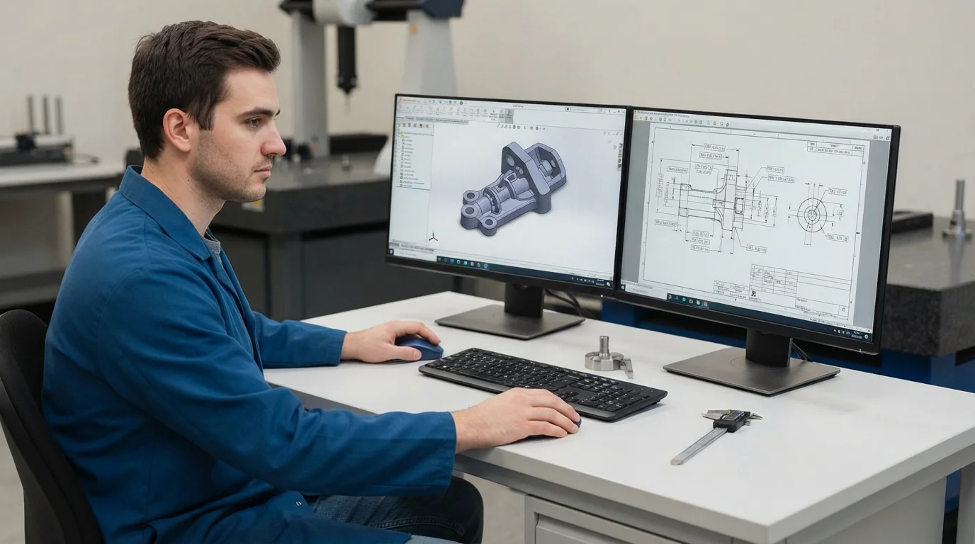
Question: What financial consequences occur when designers apply unnecessarily tight tolerances across all features of a rapid mold drawing? Over-tolerancing forces toolmakers to abandon high-speed CNC machining in favor of painstaking manual fitting, driving up NRE costs and lengthening lead times unnecessarily.
Applying strict limits like plus-or-minus 0.01 mm to every single edge of a plastic housing is fundamentally counterproductive due to natural polymer thermal shrinkage. Experienced designers reserve tight limits exclusively for critical functional interfaces while leaving general cosmetic surfaces at standard commercial tiers.
Streamlining your drafting strategy and preventing excessive financial overhead requires tracking key optimization steps:
- Isolate critical mating features—Apply tight limits only to screw bosses, hinge pins, and snap-fit latches
- Utilize general block tolerances—Establish a standard title block tolerance note for all non-critical linear dimensions
- Consult manufacturing partners early—Leverage preliminary DFM reviews to verify whether specified limits match alloy capabilities
Communicating Critical Mating Dimensions to Your Manufacturer
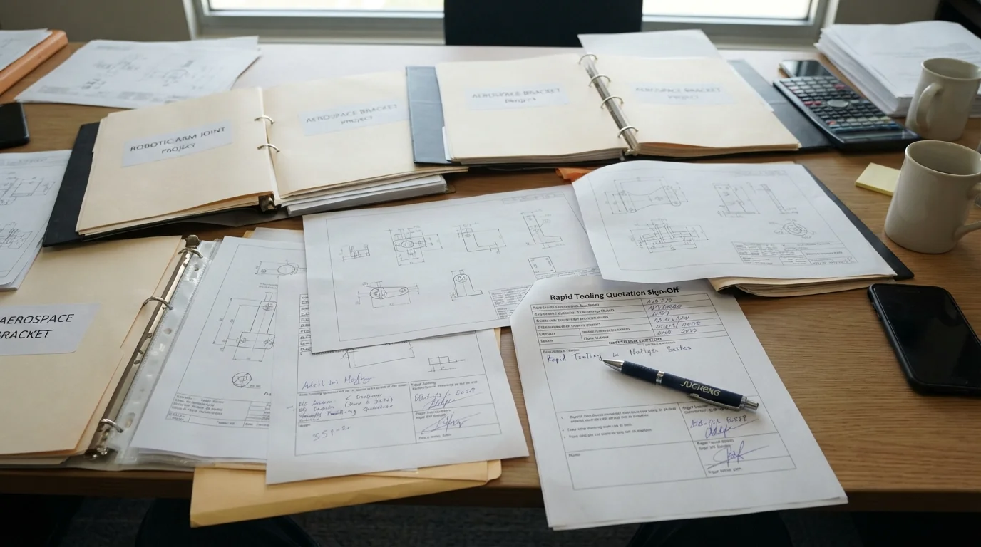
Jucheng Precision bridges the communication gap between digital design files and shop-floor execution. Backed by 150+ advanced CNC machines and an agile Vacuum Casting prototyping workflow alongside precision Prototype Service capabilities, our ISO 9001 certified engineering teams analyze every CAD submission meticulously.
Key operational advantages of our engineering review framework include:
- Comprehensive 24-hour DFM feedback—Identifying potential drawing ambiguities and tolerance conflicts instantly
- Expert drawing consultation—Helping engineers refine GD&T callouts for optimal rapid bridge mold production
- Secure file handling—Protecting your intellectual property while streamlining rapid quotation workflows
Ready to verify your engineering specifications? Upload Your CAD Files for a Free DFM Review at Jucheng Precision to ensure your drawings are ready for production.
Frequently Asked Questions (FAQ)

Why is a 3D STEP file alone not enough for manufacturing rapid injection molds?
While 3D files define geometry, they lack vital manufacturing instructions such as datum references, GD&T callouts, and specific surface finish standards required for accurate tooling.
What are the risks of over-tolerancing rapid injection molding drawings?
Over-tolerancing forces unnecessary manual toolroom adjustments, drastically driving up NRE costs and extending project lead times without providing functional value.
How does Jucheng Precision assist with CAD tolerance reviews?
Jucheng Precision provides 24-hour free DFM reviews, expert engineering consultation on GD&T callouts, and rigorous quality inspection to ensure seamless manufacturing execution.

