


Medical Device Design Guidelines: DFM for Cleanability
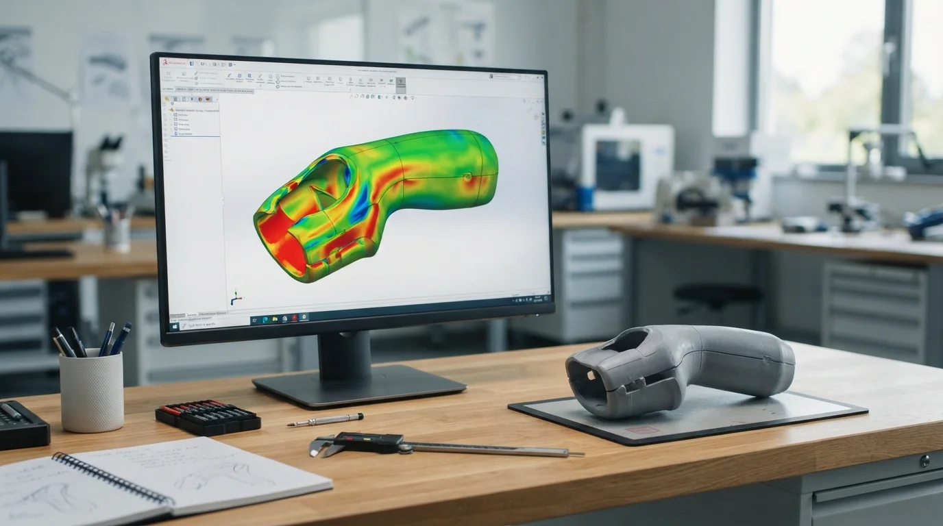
Translating clinical concepts into compliant, mass-producible healthcare hardware requires embedding manufacturing discipline into initial CAD models before cutting tool steel. When biomedical development teams draft surgical instruments or diagnostic casings, implementing comprehensive medical device design guidelines ensures that components avoid biological contamination traps while maintaining structural moldability. Designing without strict cleanability and tooling rules risks particulate accumulation, parting line flash, and costly tooling redesigns.
Utilizing an experienced contract manufacturing partner guarantees that high-performance PEEK handles, biocompatible 316L stainless steel shafts, and transparent medical polycarbonate (PC) fluid cassettes transition seamlessly into clinical validation. Let us explore the core geometric rules, human factors, and ultrasonic sealing protocols that drive compliant medical engineering.
Module 1 – Definition and Working Principles of Cleanable DFM Architecture
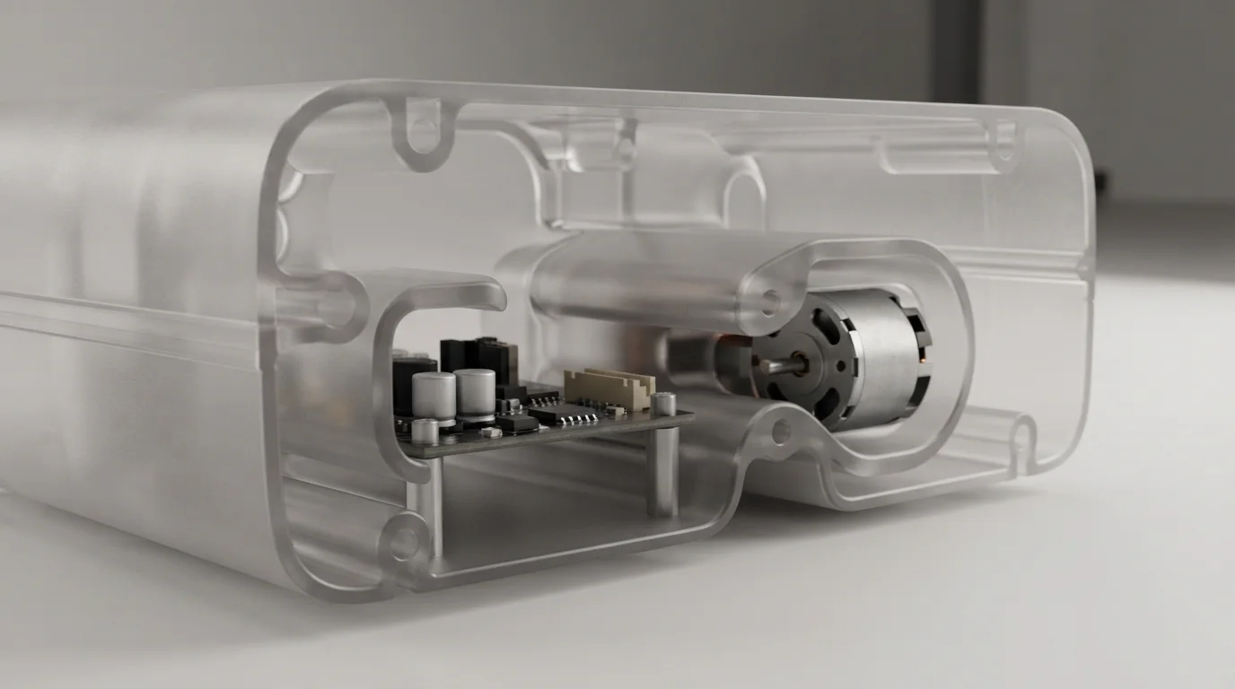
Design for Manufacturability (DFM) in healthcare engineering evaluates geometric features to ensure parts can be produced reliably, cleaned thoroughly, and sterilized repeatedly without structural degradation. The working principle relies on eliminating sharp interior corners, microscopic crevices, and unvented dead-legs where bio-burden, blood, or cleaning chemicals can stagnate. While complex profiles are often milled via CNC machining, polymer enclosures depend on precision medical injection molding to achieve smooth surface finishes.
To execute a structured cleanable design protocol on clinical hardware, mechanical designers could follow these practical steps:
- Continuous Fillet Modeling: Apply generous internal corner radii (minimum 0.8 mm to 1.5 mm) to facilitate laminar fluid flow during washing and prevent bacterial entrapment.
- Crevice Elimination: Replace split multi-part joints with single-piece molded housings or continuous laser-welded seams to seal internal electronics.
- Drainage Channeling: Incorporate gradual tapers on horizontal surfaces to ensure washdown sanitizing liquids drain off completely without pooling.
Module 2 – Core Application Scenarios
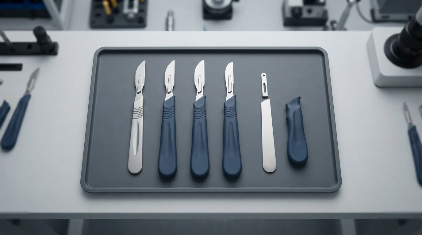
Applying specialized design rules is essential across handheld surgical tools, wearable patient monitors, and point-of-care diagnostic analyzers where ergonomic grip and hermetic seals dictate clinical efficacy. When medical innovators engineer handheld power tools, adhering to established medical device design guidelines eliminates surgeon fatigue and prevents fluid ingress into internal motor drives. Feedback from biomedical engineering groups on Reddit and Facebook indicates that integrating dual-shot overmolding with liquid silicone rubber provides the highest tactile grip during wet surgical operations.
Primary application sectors include:
- Surgical Handpieces: Designing contoured PEEK and titanium handles featuring overmolded liquid silicone rubber (LSR) grips for balanced weight distribution.
- Fluidic Diagnostic Cassettes: Engineering micro-channels with optical-grade medical ABS and polycarbonate for bubble-free reagent flow.
- Implantable Electronics: Constructing hermetically sealed titanium battery enclosures utilizing precision energy directors for laser and ultrasonic welding.
Module 3 – Key Selection Factors for Project Success
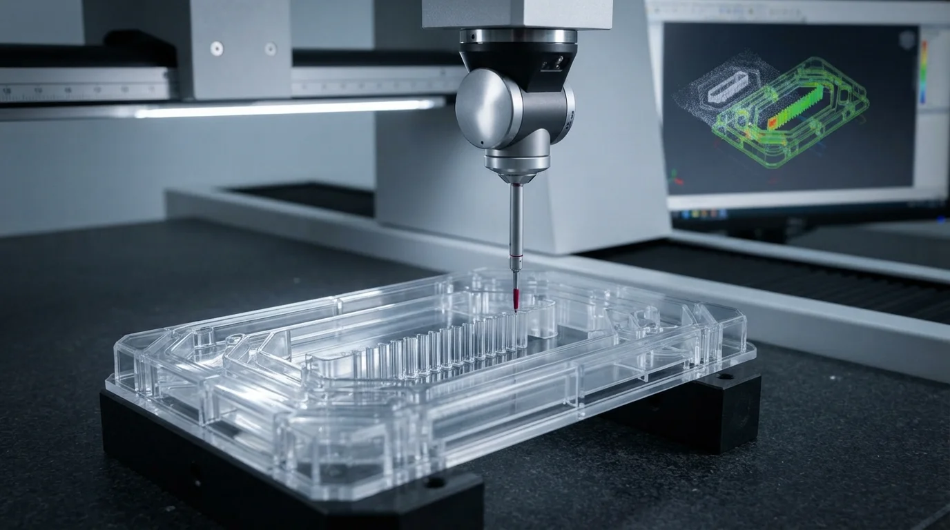
When specifying geometric parameters for medical plastic parts, engineering teams must balance nominal wall thicknesses, draft angles, and structural rib ratios. Evaluating these core parameters ensures parts mold without sink marks, warpage, or residual molded-in stress.
| Design Feature | Recommended Engineering Value | Primary Functional Benefit |
|---|---|---|
| Nominal Wall Thickness | 1.5 mm to 3.0 mm (Uniform across part) | Prevents differential shrinkage, internal voids, and structural warpage |
| Draft Angle Taper | 1.0° to 2.0° per side (3°+ for textured surfaces) | Ensures clean mold release without drag marks or surface scuffing |
| Internal Reinforcing Ribs | 50% to 60% of adjacent nominal wall thickness | Maximizes torsional rigidity while preventing cosmetic sink marks |
Module 4 – Installation and Maintenance Tips
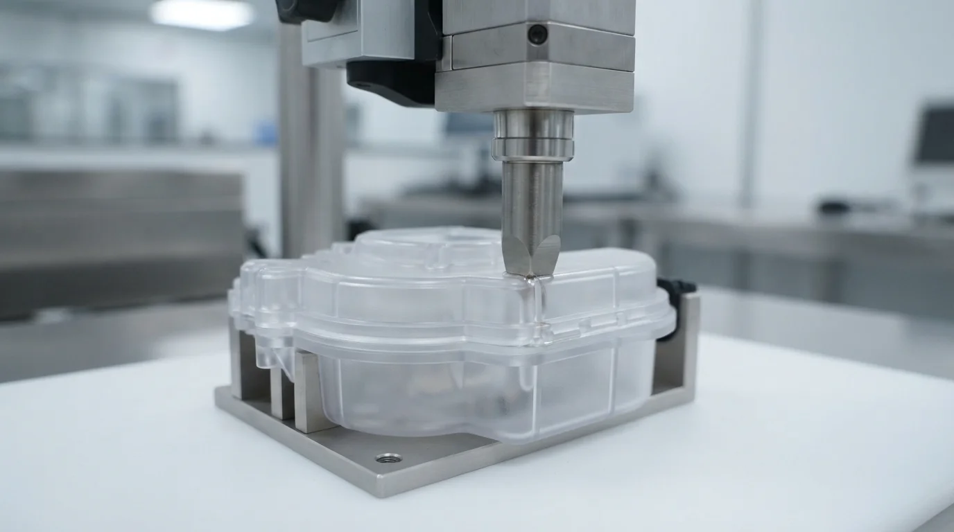
Proper joint design, ultrasonic energy director profiling, and routine sealing verification safeguard medical device enclosures throughout demanding operational lifecycles. Protecting internal electronic assemblies from cleaning solution ingress ensures long-term patient safety.
Key installation and maintenance tips include:
- Energy Director Design: Incorporate a 60° triangular energy director along tongue-and-groove mating flanges to achieve hermetic ultrasonic weld seals.
- Gasket Compression Verification: Design mechanical travel stops in CAD to prevent over-compressing elastomeric seals beyond their 25% to 30% elastic limit.
- Smooth Surface Finishing: Specify SPI-A2 diamond buffing on mold cavities to ensure molded parts release with high-gloss, easily cleanable surfaces.
Module 5 – Frequently Asked Questions (FAQ)

1. What is DFM in medical device development?
Design for Manufacturability (DFM) optimizes component geometry during the 3D CAD stage to ensure parts can be produced efficiently, cleaned easily, and assembled with high yields under medical regulatory standards.
2. Why are sharp internal corners prohibited in cleanable medical devices?
Sharp internal corners create microscopic dead zones where bodily fluids, bio-burden, and cleaning chemicals can pool, making complete sterilization impossible.
3. How does ultrasonic welding create hermetic seals on medical housings?
High-frequency acoustic vibrations melt a molded triangular energy director along tongue-and-groove joints, fusing plastic halves into a permanent, leak-proof hermetic enclosure.
4. What draft angle is required for medical-grade plastic enclosures?
Smooth medical surfaces require a minimum of 1.0° to 1.5° of draft per side, while textured or matte VDI surfaces require 3.0° or more to ensure clean mold release.
5. How do human factors influence surgical handpiece design?
Human factors engineering balances tool weight distribution, button reach, and slip-resistant silicone overmolds to maximize control and prevent surgeon hand fatigue.
6. How does Jucheng Precision assist with medical device DFM reviews?
Jucheng Precision provides automated mold flow analysis, wall thickness audits, draft angle optimization, and cleanability evaluations within 24 hours under ISO 13485 quality systems.
Module 6 – Why Choose JUCHENG for Your Project

Achieving regulatory compliance and flawless manufacturing execution requires an experienced production partner with dedicated medical engineering infrastructure. JUCHENG supports healthcare innovators by delivering comprehensive 24-hour free DFM reviews that analyze draft angles, wall uniformity, and cleanable fillet transitions prior to cutting tool steel. Founded in Shenzhen in 2012 with an 8,000-square-meter facility in Dongguan, our factory houses 150+ advanced machines, including 25+ high-performance 5-axis Haas and Mazak milling centers alongside dedicated medical molding cleanrooms.
Backed by ISO 9001, ISO 14001, ISO 13485, and IATF 16949 certifications, our engineering teams ensure that implementing robust medical device design guidelines achieves sub-micron precision, hermetic sealing integrity, and absolute batch consistency.
Ready to Optimize Your Medical Device Design for Production?
Upload your 3D models today to receive instant feedback, competitive pricing, and professional DFM analysis from our seasoned engineering experts. Let JUCHENG bring your complex designs to life with unmatched speed and reliability!

