


A first molded sample can meet the drawing while the process is still incapable of holding the same dimensions across cavities, material lots, shifts, and tool wear. Medical device injection molding tolerances must be developed as a relationship among part function, resin behavior, geometry, tooling, process control, conditioning, and measurement.
This guide explains where molded variation comes from and how to build a tolerance strategy that survives beyond the first successful setup.
Contents
- Tolerance is a variation budget
- Shrinkage is local and directional
- Geometry decides what the mold can repeat
- Tooling converts predictions into steel
- Hold a process window, not a single recipe
- Condition and measure the part correctly
- Move from first article to capability
- Tolerance planning with Jucheng
- FAQ
Tolerance Is a Variation Budget
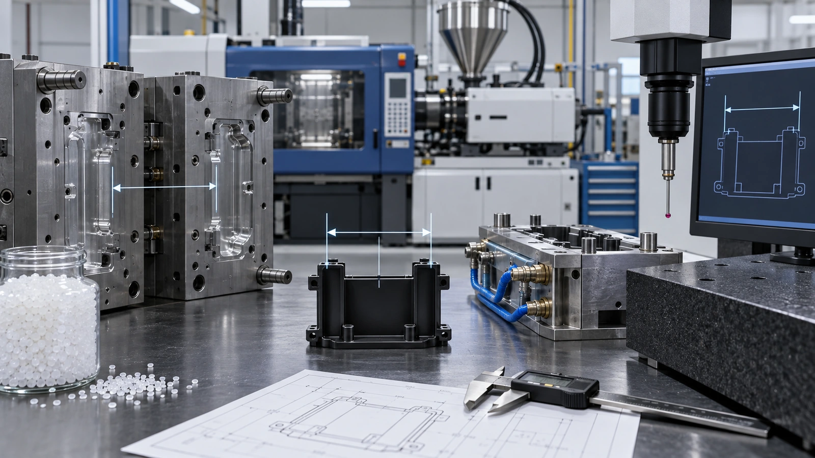
The drawing allocates how much the finished feature may vary. Molding spends that budget across cavity manufacture, resin shrinkage, machine control, temperature, pressure, cooling, moisture, part ejection, post-mold relaxation, fixture state, and measurement uncertainty. If one source consumes most of the budget, tightening inspection cannot recover it.
Start with function and assembly. Identify sealing, optical, fluidic, snap, bearing, fastening, and datum features. Use the parent guide to medical device tolerances to separate critical relationships from nonfunctional dimensions. Then allocate limits according to risk and process capability.
The most expensive molded tolerance is often the one that is tight, difficult to measure, and unrelated to device function.
Shrinkage Is Local and Directional
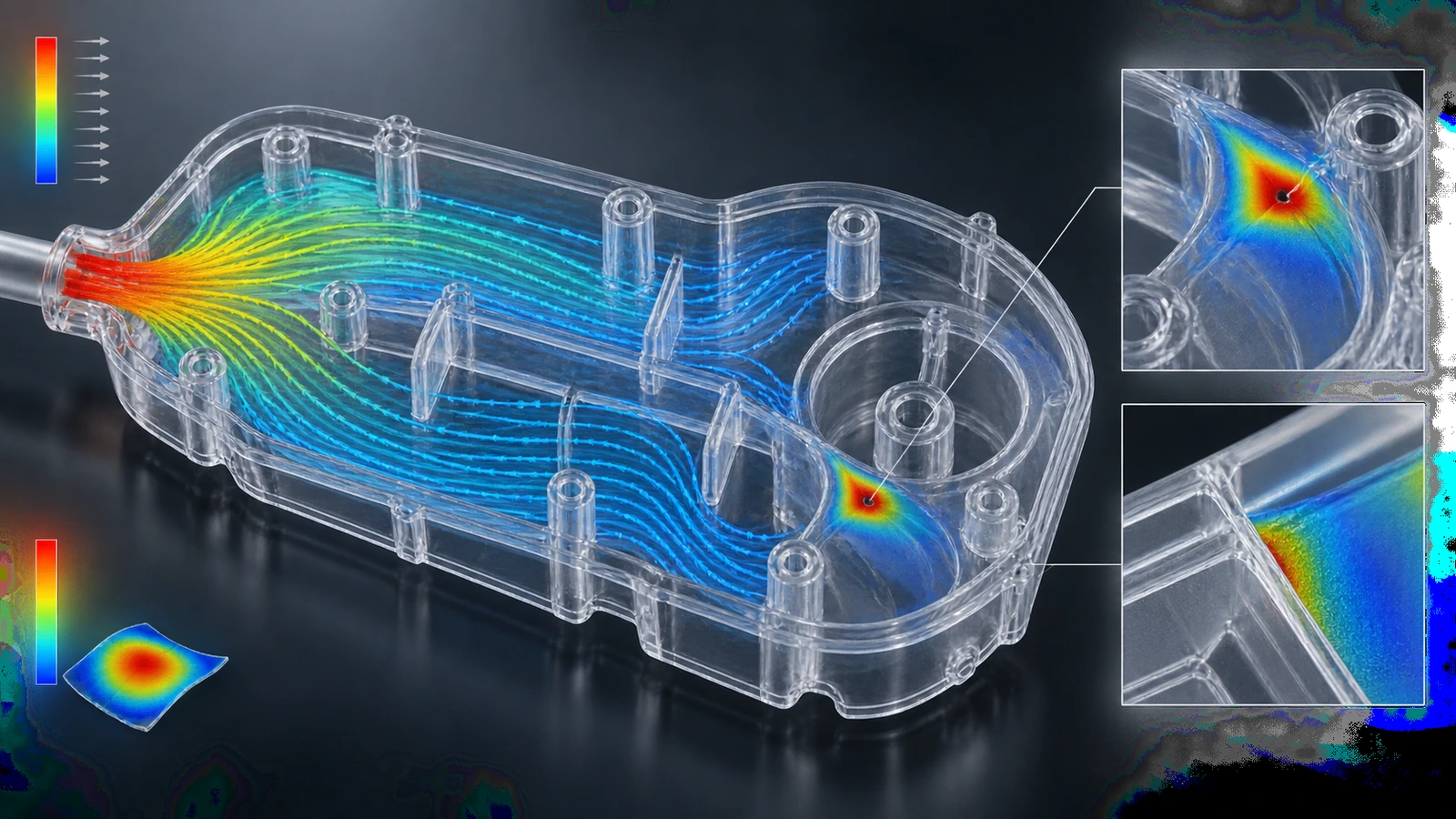
A datasheet shrinkage range is useful for early planning, but a molded part does not shrink as one uniform scale model. Flow orientation, fiber reinforcement, wall thickness, pressure transfer, gate location, cooling, crystallinity, and geometry create local and directional behavior.
Long dimensions may behave differently along and across flow. A thick boss can sink or pull a nearby wall. Ribs can restrain one area and warp another. Semicrystalline materials can continue dimensional change after ejection or under moisture and temperature exposure.
| Variation source | Typical dimensional effect | Control approach |
|---|---|---|
| Material lot or moisture | Flow, packing, shrinkage, surface change | Approved grade, storage, drying, lot records |
| Gate and pressure transfer | Local packing and differential shrinkage | Gate study, cavity-pressure understanding, balanced filling |
| Cooling imbalance | Warp, twist, ovality, post-ejection movement | Cooling design, temperature control, cycle discipline |
| Fiber orientation | Anisotropic shrinkage and mechanical behavior | Flow-aware geometry, gate location, representative testing |
Geometry Decides What the Mold Can Repeat
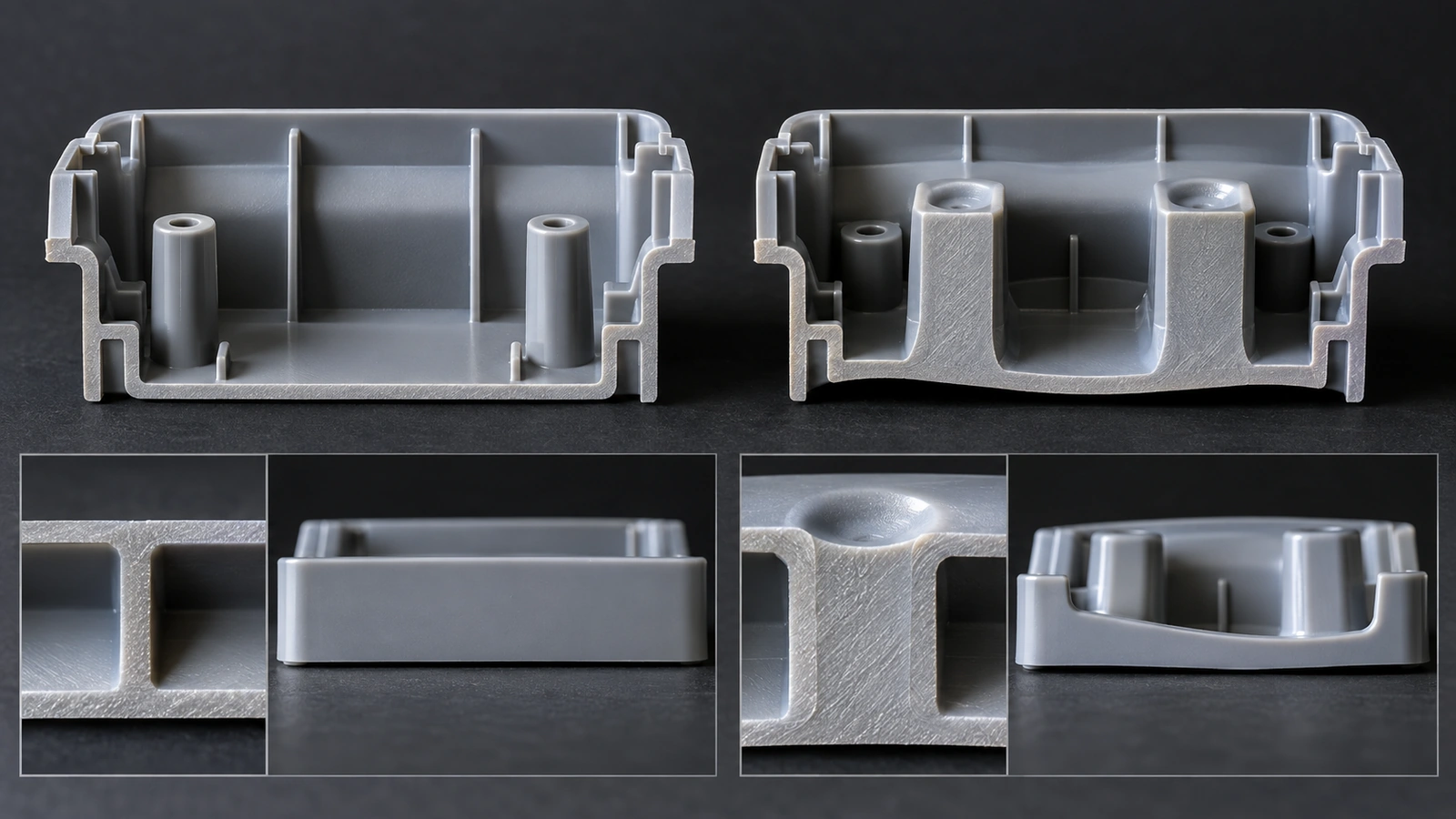
Uniform wall thickness supports consistent filling, packing, and cooling, but functional parts often need bosses, ribs, seals, threads, clips, windows, and transitions. DFM should manage these features rather than pretending every wall can be uniform.
Geometry choices that improve repeatability
- Use gradual wall transitions and appropriate radii.
- Keep thick intersections away from precision surfaces where possible.
- Support tall bosses and thin standing features without creating sink-heavy masses.
- Plan draft so ejection does not distort critical geometry.
- Place parting lines, gates, ejectors, and slides away from sealing or optical surfaces.
- Dimension functional relationships from stable, moldable datums.
- Evaluate snap and press-fit performance across temperature and moisture conditions.
A nominal CAD dimension may be measurable only when the part is constrained. Define whether acceptance applies free-state, in a fixture, or assembled. Flexible housings and thin walls can pass or fail depending on measurement support.
Tooling Converts Predictions Into Steel
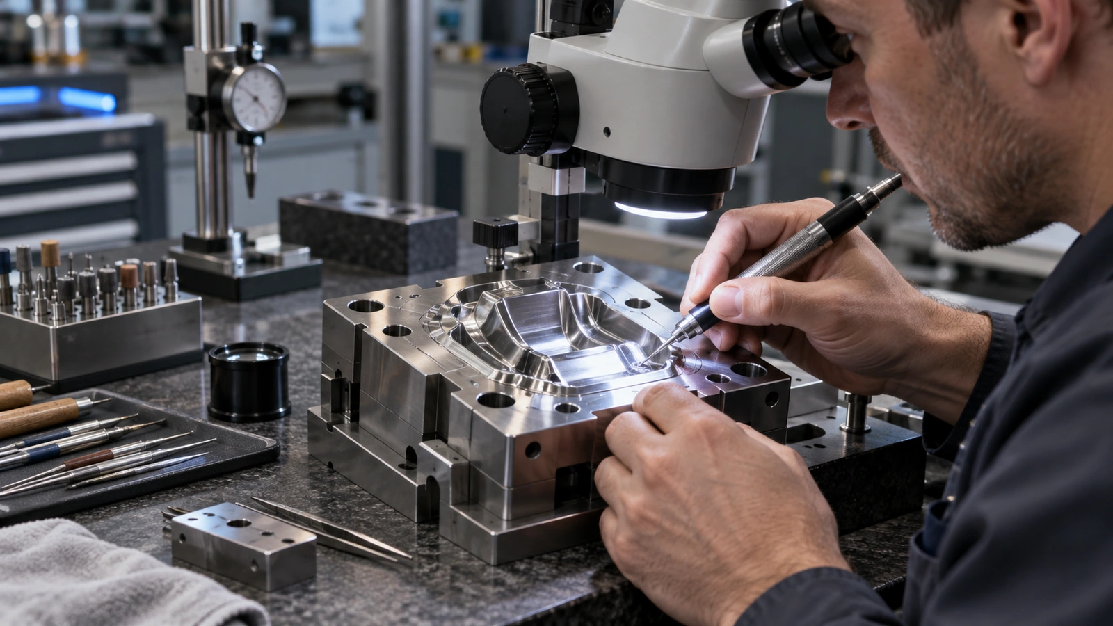
Mold design must anticipate shrinkage, venting, cooling, ejection, cavity-to-cavity balance, wear, and future adjustment. Steel-safe strategy leaves material where dimensions can be corrected after trials. Replaceable inserts can isolate high-wear or high-risk details. Cavity identification supports traceability when a multi-cavity tool behaves unevenly.
Do not use tool steel dimensions as the sole explanation for part dimensions. The process and material convert cavity geometry into the finished part. A corrective action that changes steel may solve one condition while shifting another. Use dimensional maps, process data, and functional results together.
Rapid tooling can provide production-relevant molded evidence before high-volume investment when the intended resin, gate concept, and process are represented. The rapid tooling service is useful when design learning and controlled low-volume production must happen quickly.
Hold a Process Window, Not a Single Recipe
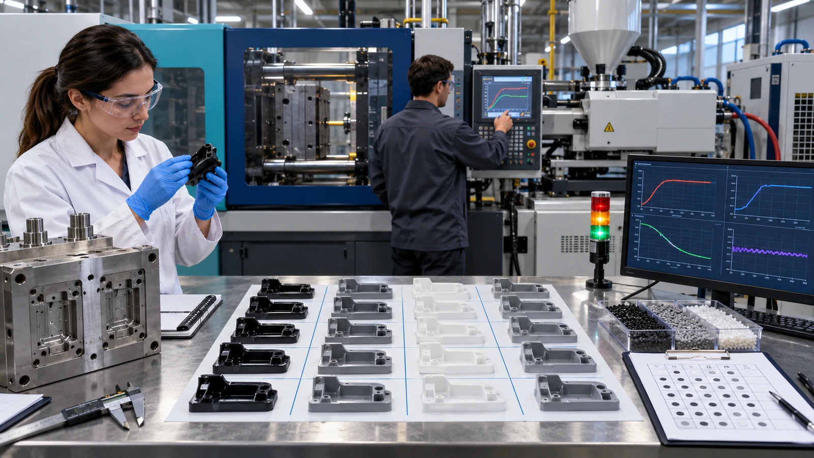
A recipe records setpoints. A process window explains which variables control the output and what range remains acceptable. Barrel temperature, mold temperature, fill rate, transfer, hold pressure and time, cushion, cooling, back pressure, clamp behavior, and material conditioning can interact.
Develop the process by understanding fill, pack, gate freeze, cooling, and ejection. Challenge meaningful high and low conditions. Monitor outputs such as part weight, cavity behavior, critical dimensions, warp, and visual defects. The goal is not to force every machine variable into the tightest possible range; it is to control the variables that materially influence the part.
For regulated production, connect the released recipe to equipment, mold, cavity, material grade, work instructions, inspection, maintenance, and change control. The wider medical device manufacturing standards context helps structure those records and responsibilities.
Condition and Measure the Part Correctly
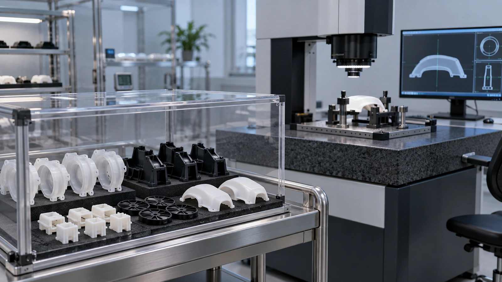
Molded dimensions can change after ejection as temperature equalizes, stress relaxes, moisture is absorbed, or crystallization continues. Define when and under what environmental condition the part is measured. If performance depends on sterilization, aging, or assembly, consider measurements and functional tests after those states.
Measurement force and fixturing can distort polymer parts. A CMM program designed for metal may overconstrain a flexible housing. Optical methods can struggle with translucent edges or texture. Create a method that represents the functional state and study repeatability across operators or setups.
The drawing or inspection plan should clarify
- Free-state, restrained, or assembled measurement condition
- Conditioning time, temperature, and humidity where relevant
- Datum simulation and fixture contact
- Measurement method for flexible, optical, or textured features
- Cavity identification and sampling logic
- Response to results near the tolerance limit
Move From First Article to Capability
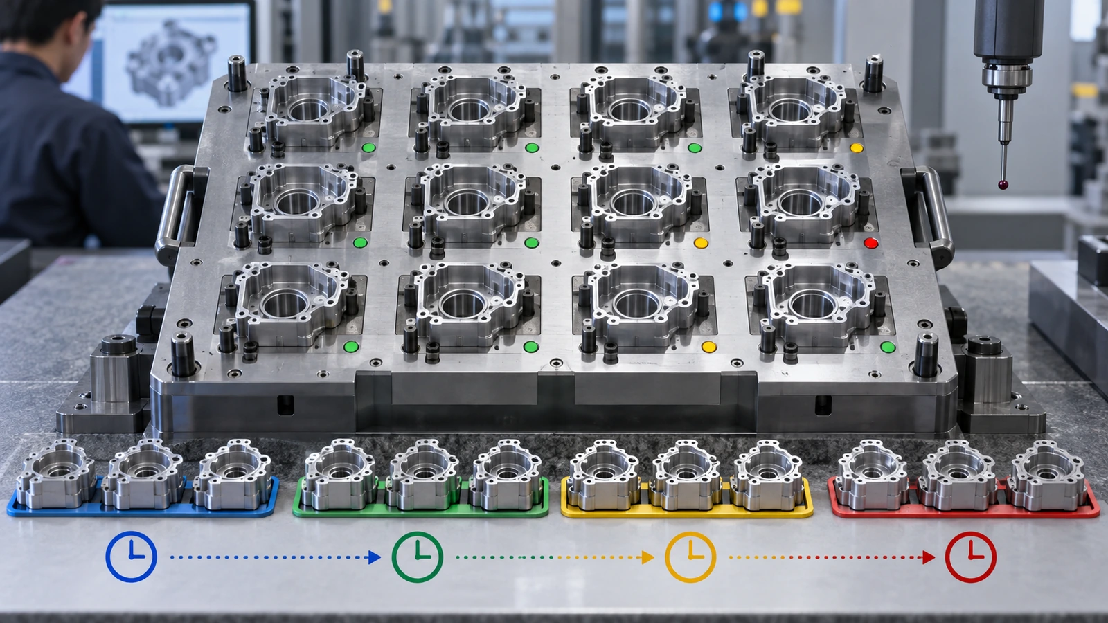
First articles show what a setup produced at one point. Capability work asks whether routine variation fits the specification across representative material, time, cavities, operators, and environmental conditions. Confirm process stability before interpreting capability statistics.
Use cavity-specific data when cavities can differ. Separate within-run variation from lot-to-lot or setup-to-setup movement. Monitor dimensions and process indicators that predict function. If a critical feature depends on an assembly relationship, include functional gauge or assembly testing rather than relying on isolated dimensions alone.
Release question: does the evidence represent routine production, or only the carefully adjusted conditions used to create the first acceptable samples?
Tolerance Planning With Jucheng
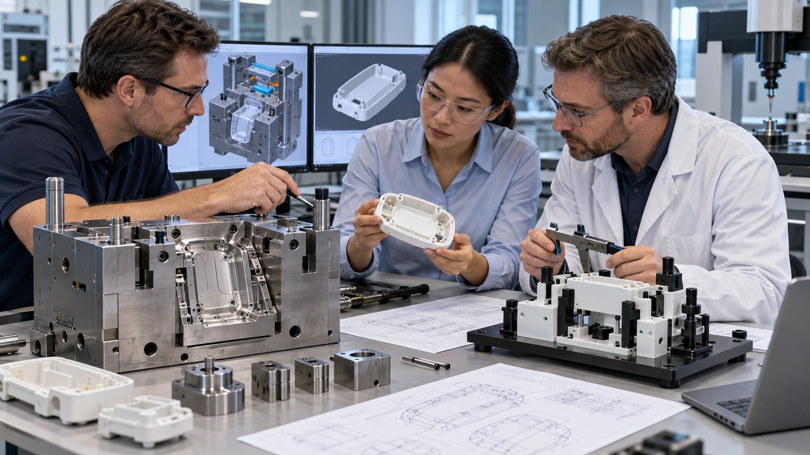
Jucheng Precision supports molded medical components from DFM and prototype comparison through rapid tooling, low-volume injection molding, inspection, and production planning. Teams can review resin, wall transitions, gate and parting-line strategy, draft, critical features, measurement state, and anticipated adjustment before cutting the mold.
Provide the model and drawing together with annual volume, exact material grade, functional interfaces, sterilization or conditioning state, CTQs, and required evidence. Jucheng can identify where tolerance risk comes from geometry, material, tooling, process, or measurement.
Injection Molding Tolerance FAQ
Can injection molding hold CNC machining tolerances?
Some molded features can be tightly controlled, but the processes have different variation sources. Resin shrinkage, flow, cooling, warp, cavities, conditioning, and flexible geometry make blanket comparisons misleading. Evaluate the specific feature and volume.
Why did a molded dimension move after the first trial?
Changes in process optimization, material condition, mold temperature, packing, cooling, tool adjustment, or measurement timing can move dimensions. The first trial is part of learning, not necessarily the released baseline.
Should every cavity use the same dimensional data set?
Cavity-specific data is valuable because steel, cooling, venting, filling, and wear can differ. Pooling data can hide one cavity that is shifted or more variable.
How soon after molding should parts be measured?
Define timing from material behavior and functional need. Some dimensions stabilize quickly; others change with temperature, stress relaxation, moisture, or crystallinity. Use a documented conditioning method.
Can tooling correction fix every tolerance problem?
No. Steel changes cannot correct an unstable process, poor material control, weak cooling, distorted ejection, or unsuitable measurement. Diagnose the variation source before modifying the mold.
Design Tolerance for the Production Distribution

Medical device injection molding tolerances are credible when they account for material, geometry, tooling, process, conditioning, measurement, and cavity behavior. A first passing part is a milestone; a controlled distribution is the production goal.
Send Jucheng your molded-part files and tolerance requirements for DFM, tooling, and process review.

