


Most flowcharts show operations as boxes: receive material, machine, clean, inspect, assemble, package. That sequence is easy to draw and too weak to control a medical device. A useful medical device manufacturing process flow chart also shows decisions, status, evidence, rework, supplier handoffs, holds, and release authority.
This article builds the chart from the questions the manufacturing system must answer. The result can support process planning, risk analysis, control plans, validation scope, training, audits, and supplier transfer without turning the diagram into unreadable decoration.
Contents
Decide What the Chart Must Control

One diagram cannot serve every audience at every level. Executives need the value stream. Manufacturing engineers need operations and parameters. Quality teams need inspections, holds, status, records, and release. Operators need controlled instructions, not a poster-sized map.
Define the product family, start and end points, manufacturing sites, supplier scope, and intended use of the chart. The parent medical device manufacturing processes page provides the thematic structure; the flow chart turns those processes into one product-specific route.
Use Three Levels of Detail

A tiered system keeps the top-level chart readable while preserving technical depth.
| Level | Purpose | Typical content |
|---|---|---|
| Level 1: value stream | Show major transformations and external boundaries | Receive, fabricate, finish, assemble, test, package, release |
| Level 2: process flow | Define operations, inspections, holds, and decisions | Machines, tools, queues, sampling, rework, records |
| Level 3: work instruction | Tell qualified people how to execute one operation | Setup, parameters, sequence, checks, safety, reaction plan |
Link the levels by document number and revision. Do not force operational instructions into the flowchart; doing so makes both the chart and the instruction difficult to maintain.
Build the Process Spine

Start with the normal path from approved inputs to released output. Use active verbs and name the transformation. Instead of process part, write CNC machine housing, ultrasonic weld cartridge, clean component, or assemble sensor module. Show queues or storage where time, environment, or status matters.
A general manufacturing spine
- Receive and identify material or purchased components.
- Verify status, specification, supplier, and required records.
- Perform primary fabrication: machining, molding, forming, printing, or casting.
- Conduct in-process checks and route according to result.
- Perform secondary work: joining, heat treatment, finishing, marking, or cleaning.
- Inspect critical characteristics and complete functional testing.
- Assemble using controlled components, fixtures, and instructions.
- Clean, package, label, and protect the defined product state.
- Review records and release or hold the lot.
Customize the spine for the product. A sterile disposable, reusable instrument, diagnostic enclosure, and robotic subassembly need different branches and evidence.
Add Decisions and Evidence
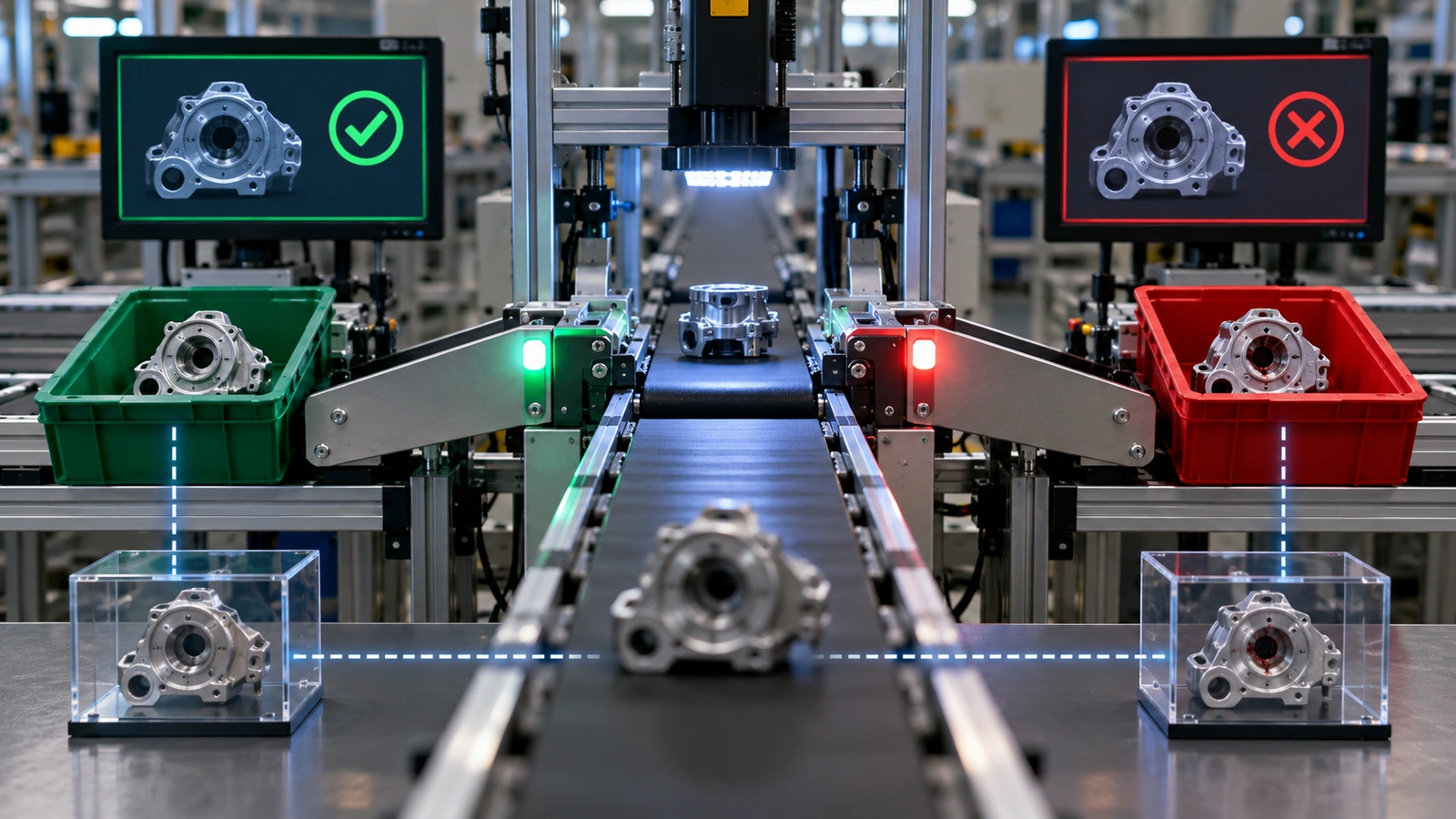
Every diamond should ask a decision that has defined criteria and authority. Material accepted? First article approved? Process within validated range? Nonconformance disposition complete? Packaging seal accepted? Records complete? Avoid vague diamonds such as quality OK without a referenced requirement.
Place record outputs beside operations: material certificate, traveler, setup approval, process log, dimensional report, special-process certificate, leak-test result, label reconciliation, or release signature. This transforms the chart into an evidence map.
Decision test: if two qualified reviewers could reach different outcomes from the same evidence, the criterion or method needs clarification.
The chart should also identify critical control points that connect with medical device quality control. Those points need measurable characteristics, methods, frequencies, and reaction plans in the control plan.
Show Rework, Scrap, and Deviation Loops

A flowchart that shows only the ideal path hides where risk accumulates. Include nonconforming material control, review, disposition, approved rework, reinspection, scrap, return to supplier, and deviation approval. Identify whether rework can repeat and what prevents endless cycling.
For each loop, define
- Who can initiate and approve the route
- Which product status and physical segregation apply
- Whether the operation changes risk or validated state
- What instruction governs the rework
- Which original and additional inspections are required
- How the device history or lot record captures the event
Do not draw use-as-is disposition as an automatic branch. It requires documented technical justification and appropriate approval. A temporary deviation should have scope, affected lots, expiration, and closure.
Make Supplier Boundaries Visible
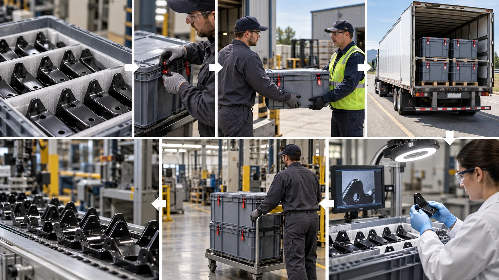
External heat treatment, coating, sterilization, molding, cleaning, testing, or packaging creates handoffs. Show shipment, status, required accompanying documents, incoming verification, and responsibility for deviations. A dashed box around supplier operations is useful only if the control points at entry and exit are explicit.
Supplier flow should align with purchase requirements and the quality agreement. Identify approved sub-tier work, change notification, traceability, transport conditions, and record retention. The medical device manufacturer selection framework helps assess whether a supplier can execute and document its assigned branch.
Connect the Chart to Validation and Controls

Use the flow to identify process steps whose outputs cannot be fully verified later. Mark validated operations, approved parameter sets, monitoring, and revalidation triggers. Show where product or process data are reviewed before the next step.
Build the process FMEA and control plan from the same route. If the FMEA contains an operation not shown on the chart, or the chart contains a decision with no control plan, the system is inconsistent. Update linked documents together through change control.
The broader requirements under medical device manufacturing standards give the chart its quality-system context: document control, records, supplier controls, validation, nonconformance, and change management.
A Worked Enclosure Example
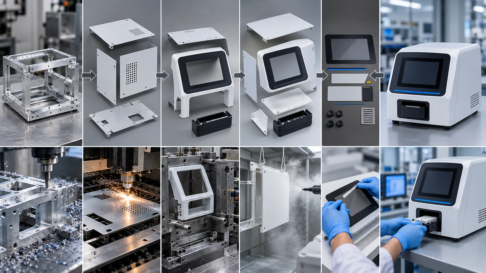
Consider a diagnostic instrument enclosure combining a machined aluminum frame, sheet-metal panels, molded front bezel, coating, printed labels, purchased fasteners, and final assembly.
- Receive: verify frame material, sheet stock, resin components, fasteners, and certificates.
- Fabricate: machine frame; cut, bend, and weld panels; mold or receive bezel.
- Inspect: approve frame datums, panel fit, bezel interfaces, and cosmetic status.
- Finish: clean, anodize or coat approved surfaces; protect grounding and sealing zones.
- Mark: apply identifiers and verify data against traveler.
- Assemble: join frame, panels, bezel, inserts, gaskets, and fasteners using controlled torque.
- Test: verify alignment, access, grounding, seal or ingress functions as applicable.
- Package: protect cosmetic and functional surfaces; reconcile labels and records.
- Release: review evidence, open deviations, and lot status.
The important additions are the decisions between these steps: Is the finish acceptable? Are grounding points free of coating? Is a deviation approved before assembly? Are identifiers reconciled before release? Those diamonds control the device more than the arrows.
Process Flow Chart FAQ

Who should create the manufacturing flow chart?
Manufacturing engineering often owns the chart, but quality, design, operations, supply chain, validation, and operators should review it. Supplier branches require supplier input and clear customer approval.
How detailed should the chart be?
Detailed enough to show transformations, status, decisions, records, handoffs, and exceptional routes without reproducing every work-instruction step. Use linked lower-level charts where complexity grows.
Should inspection be a separate box?
Show inspection when it changes status, controls progression, creates required evidence, or represents a distinct operation. Also show in-process checks inside operation documentation where appropriate.
How are rework and deviations shown?
Use explicit branches to controlled review, approved instruction, reinspection, and return to the normal path. Identify scrap and use-as-is routes separately with approval authority.
When should the flow chart be updated?
Update it when operations, sequence, site, supplier, equipment, inspection, rework, packaging, or release responsibility changes. Assess linked risk, control, validation, and training documents at the same time.
Draw the Decisions That Protect the Device

A medical device manufacturing process flow chart should reveal how approved inputs become released output and how the system responds when reality leaves the ideal path. Operations explain what happens; decisions and evidence explain how it stays controlled.
Share your product files and manufacturing scope with Jucheng to review a practical multi-process route and quotation.

