


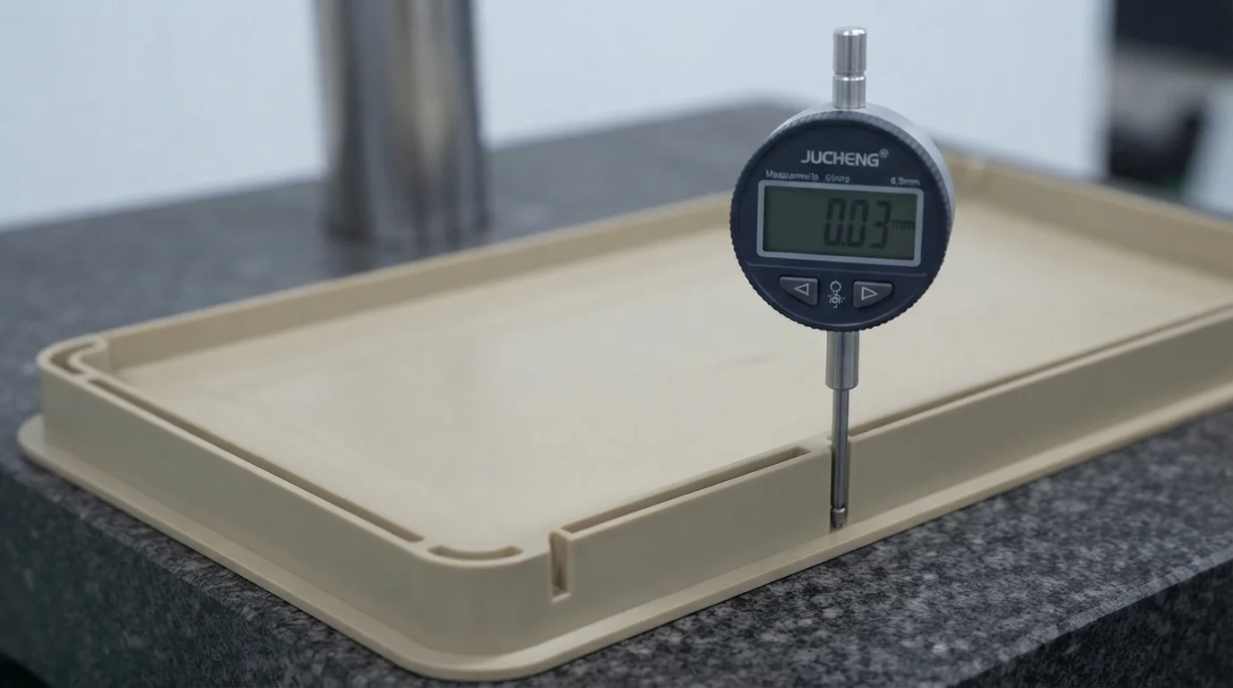
Designing injection-molded components requires strict adherence to geometry rules, particularly regarding structural cross-sections. When product designers introduce sudden transitions between thick and thin areas, cooling rates fluctuate drastically across the part, leading to severe internal stresses, visible sink marks, and unexpected warping. Maintaining proper wall thickness tolerance for rapid injection molds ensures your rapid-molded prototypes retain structural stability and crisp dimensional geometry without requiring emergency tool modifications.
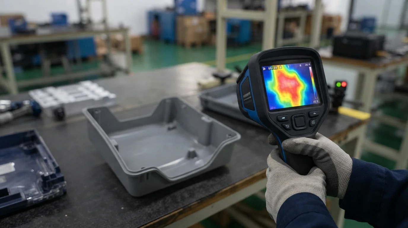
Balancing cross-sectional geometry within Rapid tooling tolerances requires respecting established engineering thresholds for common thermoplastic resins. Utilizing modular aluminum or pre-hardened steel bridge tools accelerates development schedules while processing authentic polymers under real press pressures. Let us examine the golden rules of uniform wall thickness and learn how to prevent differential shrinkage during early NPI phases.
Table of Contents
1. The Golden Rule: Uniform Wall Thickness for Tight Tolerances
2. How Variations in Wall Thickness Cause Differential Shrinkage and Warping
3. Recommended Wall Thickness Ranges for Common Engineering Plastics
The Golden Rule: Uniform Wall Thickness for Tight Tolerances
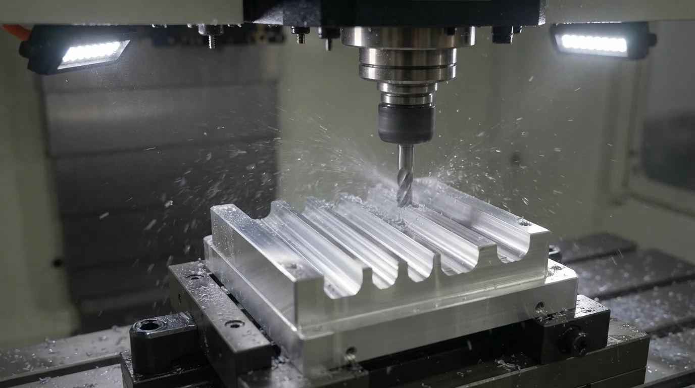
Question: Why do injection molding engineers emphasize maintaining uniform wall thickness across every section of a plastic part? Uniform cross-sections guarantee even cooling rates, preventing localized thermal stress gradients that pull parts out of tolerance.
When molten polymer flows into a rapid aluminum or steel mold cavity, thinner sections freeze almost instantly while thicker boss connections or corners retain heat much longer. This uneven cooling behavior creates internal pulling forces as the material solidifies at different rates. Utilizing an agile Injection Molding Service ensures process parameters are optimized, while a versatile Prototype Service lets engineering teams verify physical wall transitions before mass manufacturing. Sourcing precision parts through an experienced CNC Machining Service guarantees clean cavity matching.
Evaluating structural cross-sections and maintaining stable wall profiles involves monitoring specific engineering guidelines:
| Engineering Polymer | Recommended Wall Range | Max Rib Thickness (Percentage of Wall) |
|---|---|---|
| Standard ABS | 1.00 mm to 3.00 mm | 50% to 60% of nominal wall |
| Polycarbonate (PC) | 1.50 mm to 3.50 mm | 50% to 60% of nominal wall |
| Unfilled Nylon (PA6/6) | 0.75 mm to 2.50 mm | 40% to 50% of nominal wall |
How Variations in Wall Thickness Cause Differential Shrinkage and Warping
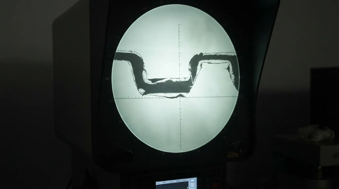
Question: What physical defects occur when a part design features abrupt transitions from thin walls to thick structural bosses? Heavy mass concentrations cool slowly, pulling surrounding material inward and creating deep surface depressions or severe structural warping.
When thick bosses intersect thin outer walls, the thick zone stays molten long after the outer skin has solidified. As this inner core finally cools, it lacks adequate packing pressure from the gate, resulting in localized volumetric collapse known as sink marks. If the transition is unmanaged, residual stress forces the entire component to bow out of flat tolerance limits.
Controlling differential shrinkage and preventing structural warping involves monitoring specific operational safeguards:
- Gradual thickness tapering—Transition walls smoothly using a 3:1 ratio rather than creating abrupt step-downs
- Hollowing out heavy bosses—Coring out thick screw posts reduces mass concentrations while preserving vertical screw retention strength
- Optimizing rib placement—Designing ribs below sixty percent of nominal wall thickness prevents surface sink blemishes
Recommended Wall Thickness Ranges for Common Engineering Plastics
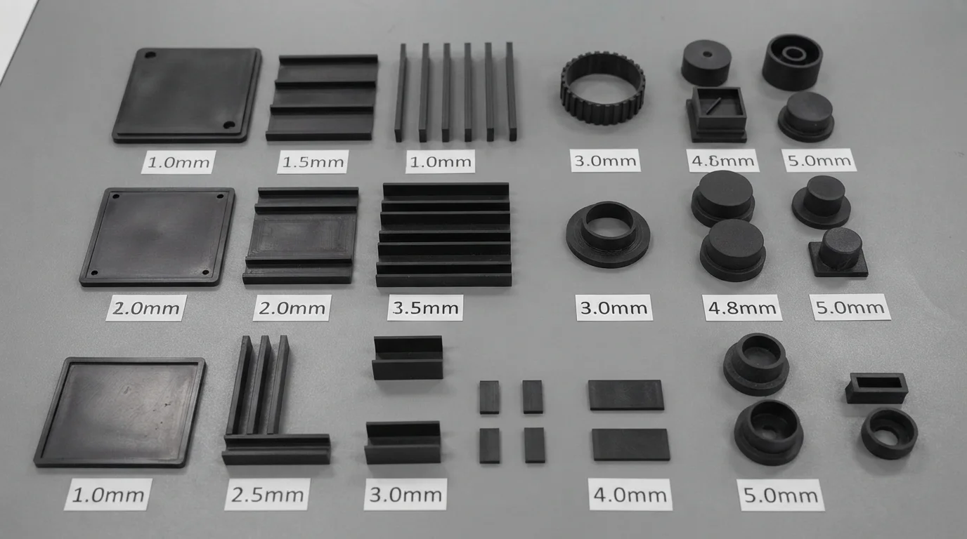
Question: How does Jucheng Precision assist hardware developers in optimizing wall profiles prior to tool cutting? Expert engineering review teams analyze 3D CAD geometries, providing comprehensive feedback on wall thickness uniformity and gate placement.
Jucheng Precision supports hardware innovators by delivering comprehensive 24-hour free DFM reviews that evaluate wall thickness distribution risks prior to cutting metal. Operating with 150+ advanced CNC machines—including 25 high-precision 5-axis systems—alongside 35+ specialized injection molding presses, our ISO 9001 certified facilities ensure absolute quality control. Sourcing expert engineering guidance guarantees your rapid-molded components maintain tight dimensional tolerances.
Partnering with an internationally certified manufacturer guarantees full material traceability and robust tooling performance. Key operational advantages of our precision manufacturing framework include:
- Expert DFM wall optimization—Identifying structural pinch points and sink mark risks before tool fabrication
- Precision high-speed machining—Carving accurate mold cavities across 35+ dedicated injection molding workstations
- Zero minimum order constraints—No MOQ policies allow exact inventory alignment with customized pilot production runs
Frequently Asked Questions (FAQ)
Why is uniform wall thickness critical for maintaining rapid injection mold tolerances?
Uniform wall sections ensure even cooling rates across the entire component, preventing thermal stress gradients that cause warping and out-of-tolerance dimensions.
What manufacturing defects occur when wall thicknesses transition too abruptly?
Abrupt thickness transitions create heavy mass concentrations that cool slowly, resulting in surface sink marks, internal voids, and severe structural warpage.
How does Jucheng Precision help optimize plastic wall thickness design?
Jucheng Precision provides 24-hour free DFM reviews, expert engineering guidance, and precision rapid injection molding to ensure stable, warp-free component production.

