


A solar inverter enclosure can be perfectly sealed and still fail because heat has nowhere to go. It can also run cool in a laboratory and fail outdoors when sun, dust, humidity, insects, cable loads, and installation errors arrive together. The enclosure must solve both sides of that conflict.
Good solar inverter enclosure design starts at the heat-generating components, follows every thermal interface to the outside air, and then builds weather protection, electrical separation, service access, and manufacturability around that path.
Trace Heat From the Semiconductor to the Sky
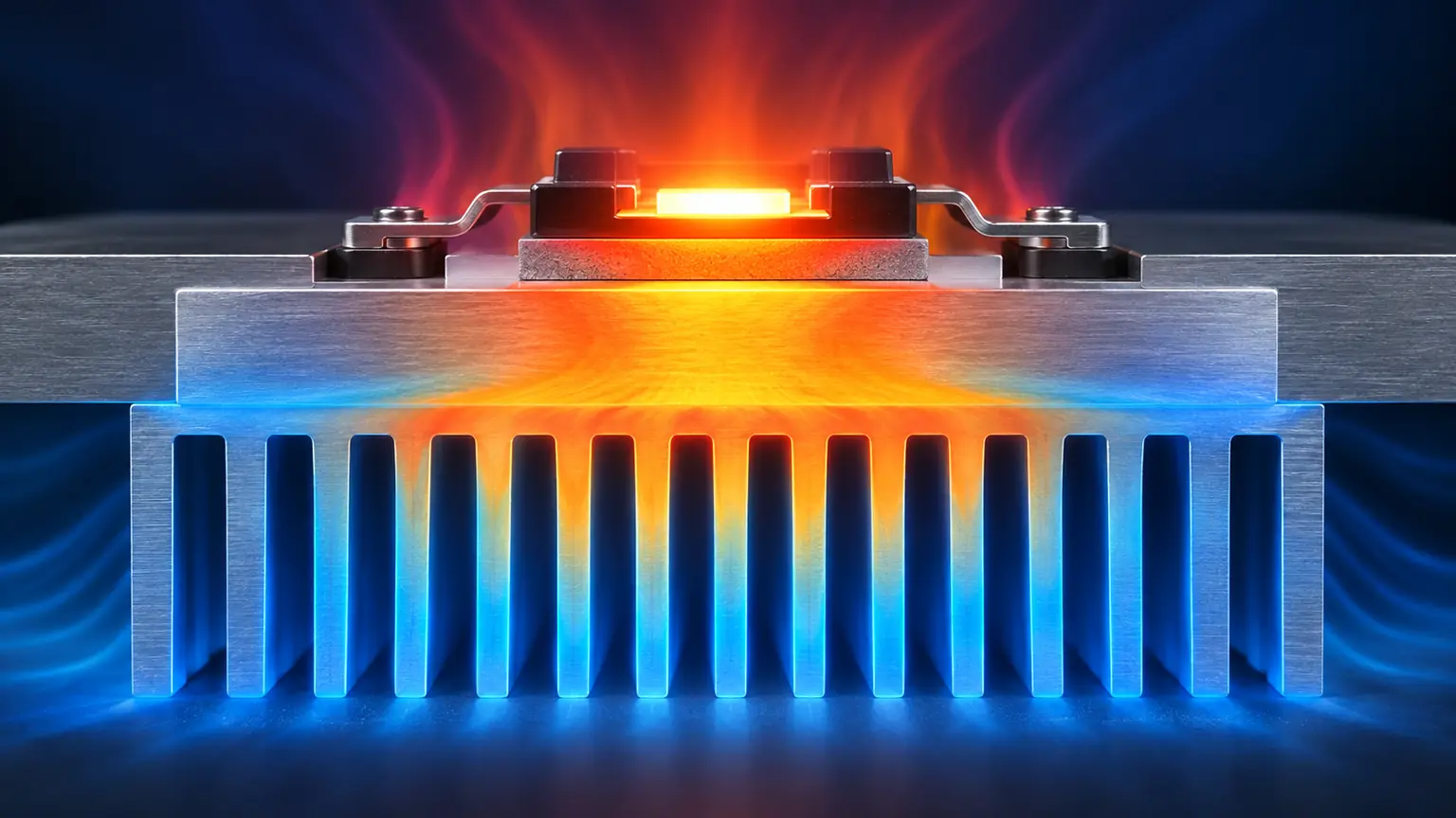
Power semiconductors, magnetics, capacitors, busbars, filters, and control electronics create different heat loads and have different temperature limits. Map continuous and peak losses, then identify every interface: device to thermal pad, pad to heat spreader, spreader to heat sink or cold plate, enclosure wall to ambient air.
The weakest interface can dominate the whole path. A large external heat sink cannot compensate for poor flatness, uneven mounting pressure, a thick thermal interface layer, or trapped air behind the power module. Define contact area, finish, flatness, fastener pattern, and assembly torque where thermal performance depends on them.
For prototype and low-volume thermal hardware, a CNC-machined heat sink allows fin geometry, mounting datums, sealing lands, and interface thickness to change without an extrusion die.
Do not ignore solar gain
Outdoor surfaces absorb solar energy before the inverter starts operating. Orientation, shade, roof overhang, coating color, air gap, and mounting wall all change enclosure temperature. A thermal model and test plan should include the installed orientation rather than treating ambient air temperature as the only boundary.
The Site Writes Part of the Specification
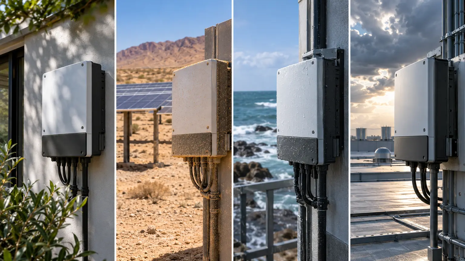
A shaded residential wall, a desert ground-mount array, a coastal installation, and a dusty industrial roof are not equivalent environments. Record temperature extremes, solar exposure, altitude, salt, blowing dust, rainfall, ice, insects, installation clearance, and likely maintenance practice.
Weather protection should use layers. A sloped top and drip edge reduce direct water load. A labyrinth or hood protects ventilation paths. Stable gasket compression guards doors and removable panels. Drainage keeps external recesses from holding water. Coating and compatible fasteners manage corrosion after fabrication.
Material selection often balances coated steel, aluminum, and stainless steel. Aluminum reduces weight and spreads heat well; steel provides stiffness economically; stainless steel can justify its cost in aggressive environments. The final choice must include panel geometry, joining, finish, galvanic interfaces, and mounting loads.
Inside the Box, Keep Power, Control, and Service From Colliding
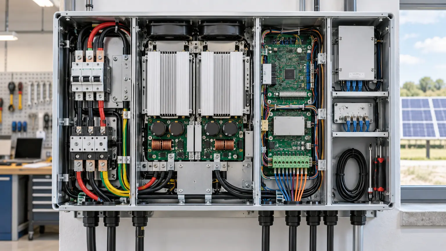
Separate high-voltage power areas from communications and user-accessible zones. Give busbars and cables realistic bend radii, support, isolation, and assembly sequence. Keep temperature-sensitive capacitors away from local hot zones. Place replaceable fans, filters, fuses, and communication modules where technicians can reach them without dismantling the heat path.
Electromagnetic compatibility also influences the metalwork. Conductive joints, bonding points, shield termination, aperture size, cable entry, and seam continuity should be coordinated with electrical design. A painted joint is not automatically a reliable electrical bond, and an insulating gasket may interrupt a shielding path.
Condensation appears during transitions
Night cooling, morning sun, rapid power changes, and door opening can move surfaces through dew point. Review insulation, ventilation, sealed volume, heaters, drains, coatings, sensor placement, and control logic. Water formed inside the enclosure needs as much attention as rain outside it.
Red-Line These Mechanical Details Before Release
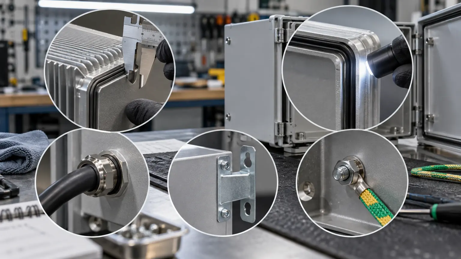
| Drawing area | Question for the review | Manufacturing consequence |
|---|---|---|
| Heat-sink opening | Which surface seals and which surface transfers heat? | Flatness, masking, gasket land, fastener pattern |
| Door perimeter | Is compression uniform after welding and coating? | Stiff returns, latch spacing, fixture and inspection |
| Cable entry | Can field cables be installed without side-loading glands? | Plate access, tool clearance, strain relief |
| Wall mounts | Where do weight and service loads enter the frame? | Reinforcement and weld load path |
| Bonding points | How is coating controlled at electrical contacts? | Masking, studs, washers, verification |
Large flat panels, sharp internal corners, inaccessible welds, and uniformly tight tolerances are warning signs. A fabricator can often replace thickness with formed stiffness, open corner radii for tools, or move precision into a machined interface.
Early review by a sheet metal fabrication team helps align bends, weld sequence, inserted hardware, sealing planes, and coating with the inverter’s functional datums.
Prototype by Failure Mode, Not by Appearance
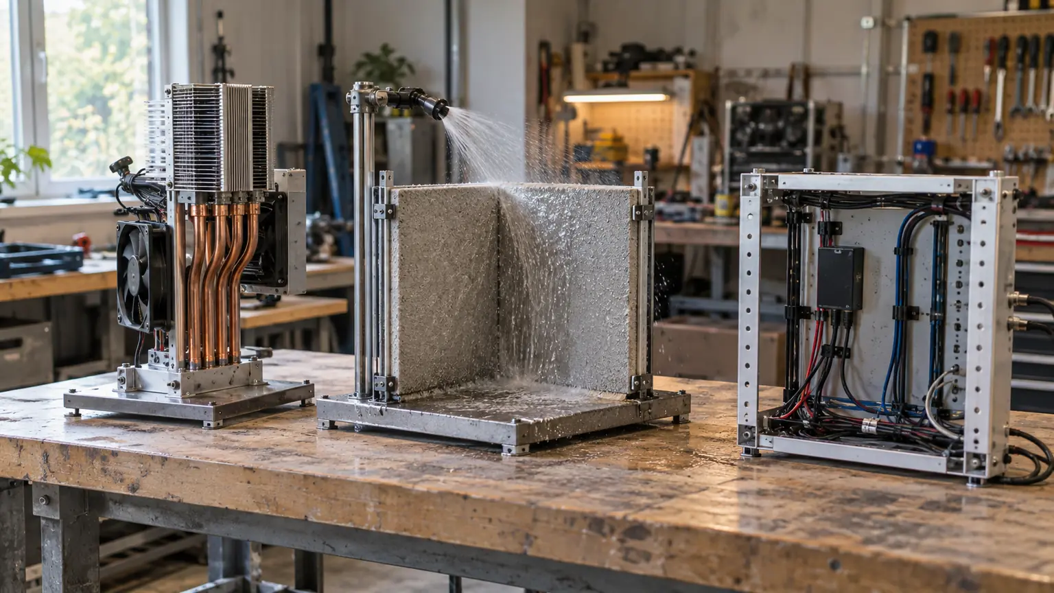
A polished full enclosure may answer fewer questions than three rough but purposeful test articles.
Thermal spine prototype
Build the power-module mount, interface material, heat spreader, heat sink or cold plate, and representative enclosure boundary. Measure contact behavior and temperatures under a defined load.
Weather corner prototype
Include a top seam, door corner, gasket, latch, coating, fastener, and drain. Challenge the real geometry with the specified ingress method and inspect the entry path.
Service bay prototype
Use representative modules, cables, connectors, and tools to confirm installation and replacement. A 3D-printed duct or mock power module can expose access problems before expensive electronics are available.
Jucheng Precision’s rapid prototyping service can combine machined thermal parts, formed enclosures, printed airflow parts, and finished assemblies in these risk-driven builds.
The Manufacturing Handoff Needs More Than a CAD File
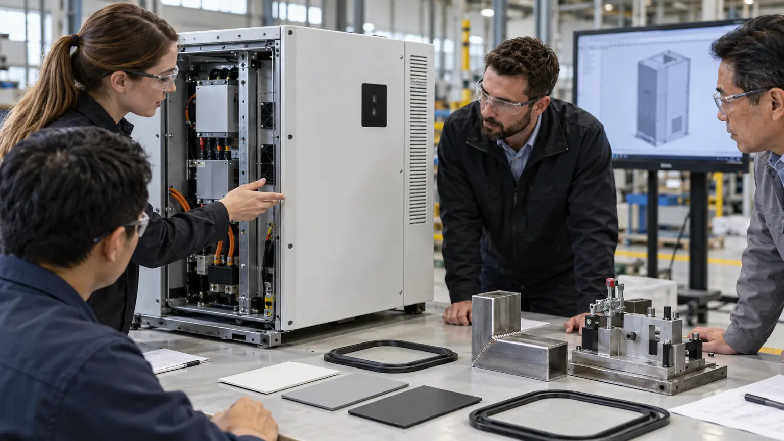
Release the operating environment, material and temper, finish, cosmetic zones, functional datums, sealing surfaces, weld class, hardware, masking, grounding points, critical tolerances, inspection method, thermal-interface requirements, and test responsibility. Include expected prototype and production quantities.
Identify which requirements belong to the complete inverter rather than the bare enclosure. A cabinet supplier can verify panel dimensions and sealing geometry, but system-level thermal, electrical, ingress, and compliance performance depends on the assembled product and its approved test plan.
Questions That Improve a Solar Inverter Design Review
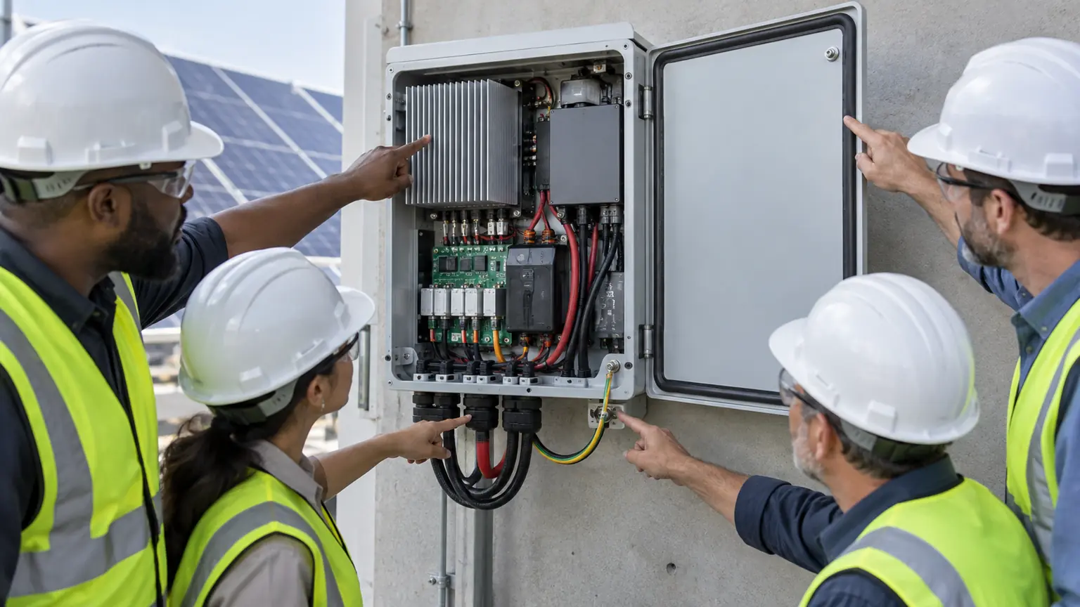
Should the heat sink be part of the enclosure wall?
It can be, especially when a sealed internal volume is needed. The design must coordinate thermal contact, structural support, gasket sealing, corrosion, and service removal at the same interface.
Is aluminum always preferred for inverter housings?
No. Aluminum is light and thermally conductive, but steel or stainless can be better when stiffness, cost, vandal resistance, or aggressive exposure dominates.
How much clearance should surround an outdoor inverter?
Use the system manufacturer’s thermal and installation requirements. Clearance depends on airflow pattern, heat rejection, wall temperature, solar exposure, adjacent units, and service access.
What should be inspected first on a pilot enclosure?
Start with thermal mounting surfaces, sealing planes, cable-entry geometry, door and latch alignment, wall mounts, bonding points, and the dimensions that locate internal modules.
The Best Enclosure Makes Heat and Weather Predictable
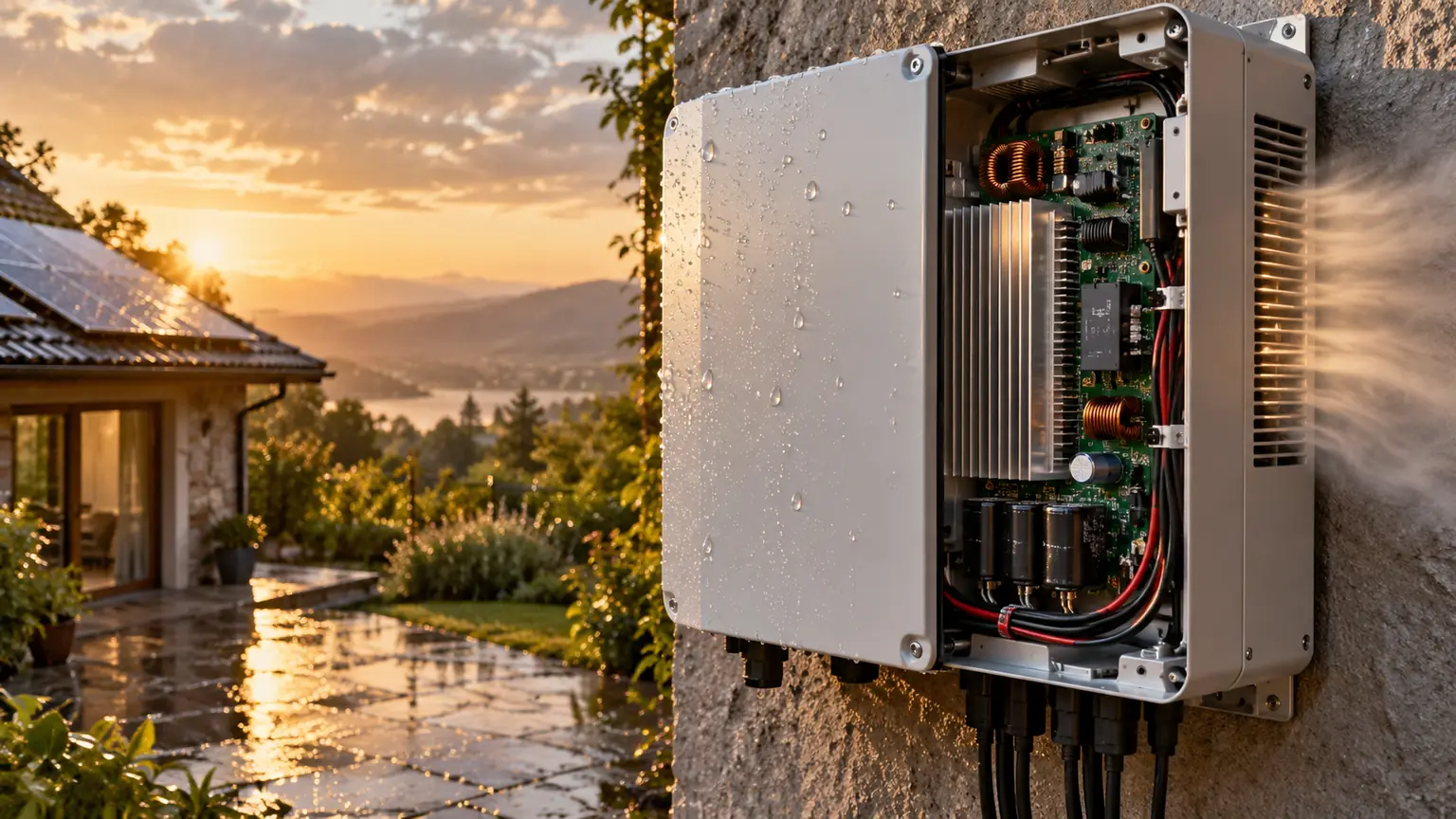
A solar inverter enclosure succeeds when its thermal path, outdoor defenses, electrical zones, service operations, and manufacturing controls reinforce each other. Design from the power device outward, and the box becomes an engineered part of the inverter rather than a late protective cover.

