


Designing individual plastic components to meet specific standalone drawing dimensions represents only half of the mechanical engineering battle. When multiple injection-molded parts must integrate smoothly within a complex housing assembly, microscopic dimensional variances from each individual component begin compounding upon one another. This cumulative phenomenon can transform seemingly acceptable parts into an assembly disaster where latches refuse to engage and structural panels warp under binding stress. Mastering tolerance stack up in rapid injection molding ensures your multi-part designs achieve flawless mechanical alignment right from initial pilot builds.
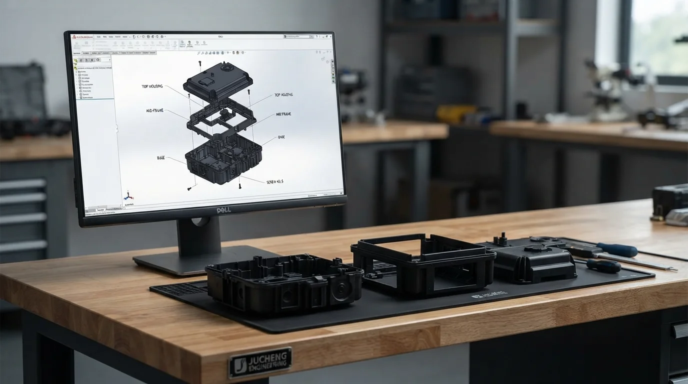
Analyzing cumulative variation within Rapid tooling tolerances requires shifting focus from isolated linear measurements to holistic assembly-driven engineering. Utilizing modular aluminum or pre-hardened steel bridge tools accelerates design iterations while injecting genuine engineering polymers under real press pressures. Let us examine how cumulative variation develops across multi-part housings and discover strategies to prevent assembly failure.
Table of Contents
1. What is Tolerance Stack-Up? The Multi-Part Assembly Challenge
2. Multi-Cavity Mold Variations and Cavity-to-Cavity Shifts
What is Tolerance Stack-Up? The Multi-Part Assembly Challenge
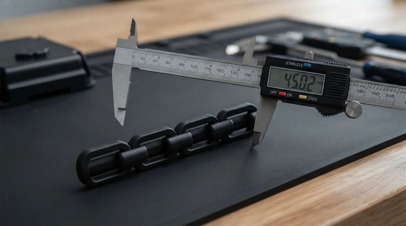
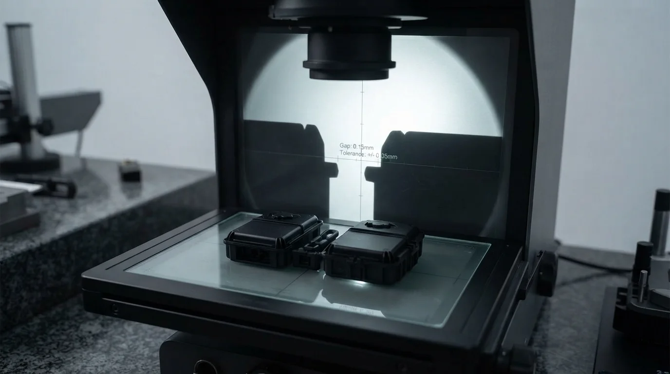
Question: Why do assemblies fail even when every individual molded component measures within its specified CAD drawing tolerance? Minor individual variations compound sequentially along a linear dimension chain, creating massive cumulative clearance errors.
Consider a handheld enclosure comprising a top shell, an internal electronic bracket, a mid-frame gasket, and a bottom cover. If each separate part drifts toward the maximum allowable positive or negative limit, the final stacked assembly can exhibit a gap or interference exceeding half a millimeter. Utilizing an agile Injection Molding Service ensures process stability, while an experienced Prototype Service lets mechanical teams evaluate physical assembly stacks before committing to mass production. Sourcing precision parts through a specialized CNC Machining Service guarantees rigid metal interface frames match polymer mating surfaces precisely.
Evaluating cumulative variation across linear feature chains involves tracking specific engineering design metrics:
| Assembly Tier | Individual Part Tolerance | Cumulative Stack Error (4-Part Chain) |
|---|---|---|
| Standard Commercial Tier | ±0.10 mm per part | Up to ±0.40 mm total variance |
| Precision Rapid Tooling Tier | ±0.05 mm per part | Up to ±0.20 mm total variance |
| Fine Precision Class | ±0.02 mm per part | Up to ±0.08 mm total variance |
Multi-Cavity Mold Variations and Cavity-to-Cavity Shifts
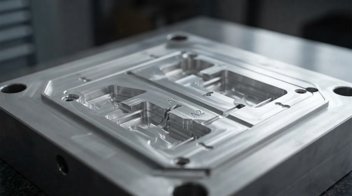
Question: How do multi-cavity rapid molds introduce unexpected dimensional shifts between identical parts in the same production batch? Slight micro-machining variations between individual cavity pockets and uneven runner lengths create subtle cavity-to-cavity discrepancies.
When rapid bridge molds feature multiple cavities to accelerate output, molten plastic fills each pathway under slightly distinct thermal and pressure gradients. Parts originating from Cavity A1 may measure marginally different from parts ejected from Cavity A2, complicating assembly lines if components get randomly mixed. Implementing strict lot traceability and targeted metrology checks prevents mixed-cavity interference during final product assembly.
Controlling cavity-to-cavity variations and minimizing cumulative stack error requires monitoring specific operational safeguards:
- Balanced runner layout design—Symmetrical runner routing ensures identical fill timing and pressure drops across all mold cavities
- Cavity-specific part identification—Laser-engraving subtle cavity markers allows sorting and traceability during multi-part assembly
- Targeted CMM inspection audits—Measuring parts sampled specifically from every individual cavity verifies uniform dimensional output
Assembly-Driven Tolerancing: Designing for Perfect Fit
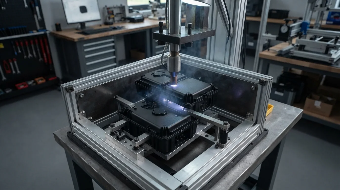
Question: How does Jucheng Precision support engineering teams in resolving complex multi-part tolerance stack issues? Expert technical review teams analyze complete 3D assembly stacks, offering DFM optimizations and in-house assembly validation to guarantee flawless physical fit.
Jucheng Precision supports hardware developers by delivering comprehensive 24-hour free DFM reviews that evaluate multi-part interaction risks prior to cutting metal. Operating with 150+ advanced CNC machines—including 25 high-precision 5-axis systems—alongside 35+ specialized injection molding presses, our ISO 9001 certified facilities ensure absolute quality control. Sourcing expert engineering guidance guarantees your assemblies fit together right the first time.
Partnering with an internationally certified manufacturer guarantees full material traceability and robust tooling performance. Key operational advantages of our assembly-focused manufacturing framework include:
- Holistic assembly analysis—Identifying potential cumulative gap and interference risks across multi-part CAD chains
- In-house mechanical validation—Assembling pilot components within our facility to verify real-world tactile fitment
- Zero minimum order constraints—No MOQ policies allow exact inventory alignment with customized pilot production runs
Frequently Asked Questions (FAQ)
What causes tolerance stack-up issues in rapid injection molded assemblies?
Tolerance stack-up occurs when minor dimensional variances from multiple individual mating parts compound sequentially along a linear dimension chain, resulting in assembly gaps or binding interference.
How do multi-cavity rapid molds affect part consistency across a batch?
Slight micro-machining differences between individual cavity pockets and uneven runner lengths can create subtle cavity-to-cavity dimensional shifts within the same production batch.
How does Jucheng Precision help prevent multi-part assembly failures?
Jucheng Precision provides 24-hour free DFM reviews, holistic assembly stack evaluations, and in-house physical fitting to ensure your multi-part rapid-molded products assemble flawlessly.

